Appendix-1 Instructions for UL
◆
Drive Motor Overload Protection
Set parameter
0
2-01 (motor rated current) to the appropriate value to enable motor overload protection. The internal motor overload protection is
UL listed and in accordance with the NEC and CEC.
■
02-01 Motor Rated Current
Setting Range: Model Dependent
Factory Default: Model Dependent
The motor rated current parameter (
0
2-01) protects the motor and allows for proper vector control when using open loop vector or flux vector
control methods (
00
-0
0
=
1
). The motor protection parameter
08
-0
5
is set as factory default. Set
0
2-01 to the full load amps (FLA) stamped on
the nameplate of the motor.
The operator must enter the rated current of the motor (
02
-0
1
) in the menu during auto-tuning.
SICP_C710616_28B_1_0.book Page 552 Wednesday, May 13, 2009 4:50 PM
■
Motor Overload Protection Selection
The drive has an electronic overload protection function (
O
L1) based on time, output current, and output frequency, which protects the motor from
overheating. The electronic thermal overload function is UL-recognized, so it does not require an external thermal overload relay for single motor
operation.
This parameter selects the motor overload curve used according to the type of motor applied.
Overload Protection Settings
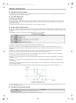
Sets the motor overload protection function in 08 group according to the applicable motor.
Setting 08-05 = 0. Disables the motor overload protection function when two or more motors are connected to a single inverter. Use an
alternative method to provide separate overload protection for each motor such as connecting a thermal overload relay to the power line of
each motor.
Setting
08
-
12
=
1.
To protect HVAC load(FANPUMP…so on)as long as the load is less than 113% rated current, the motor continue to run.
The load is larger than 123% rated current, the motor will run for 1 minute.
Setting
08
-
11
=
0.
For motors without a forced cooling fan (general purpose standard motor), the heat dissipation capability is lower when in
low speed operation.
Setting
08
-
11
=
1.
For motors with a forced cooling fan (inverter duty or V/F motor), the heat dissipation capability is not dependent upon
the rotating speed.
To protect the motor from overload by using electronic overload protection, be sure to set parameter 02-01 according to the rated current value
shown on the motor nameplate.
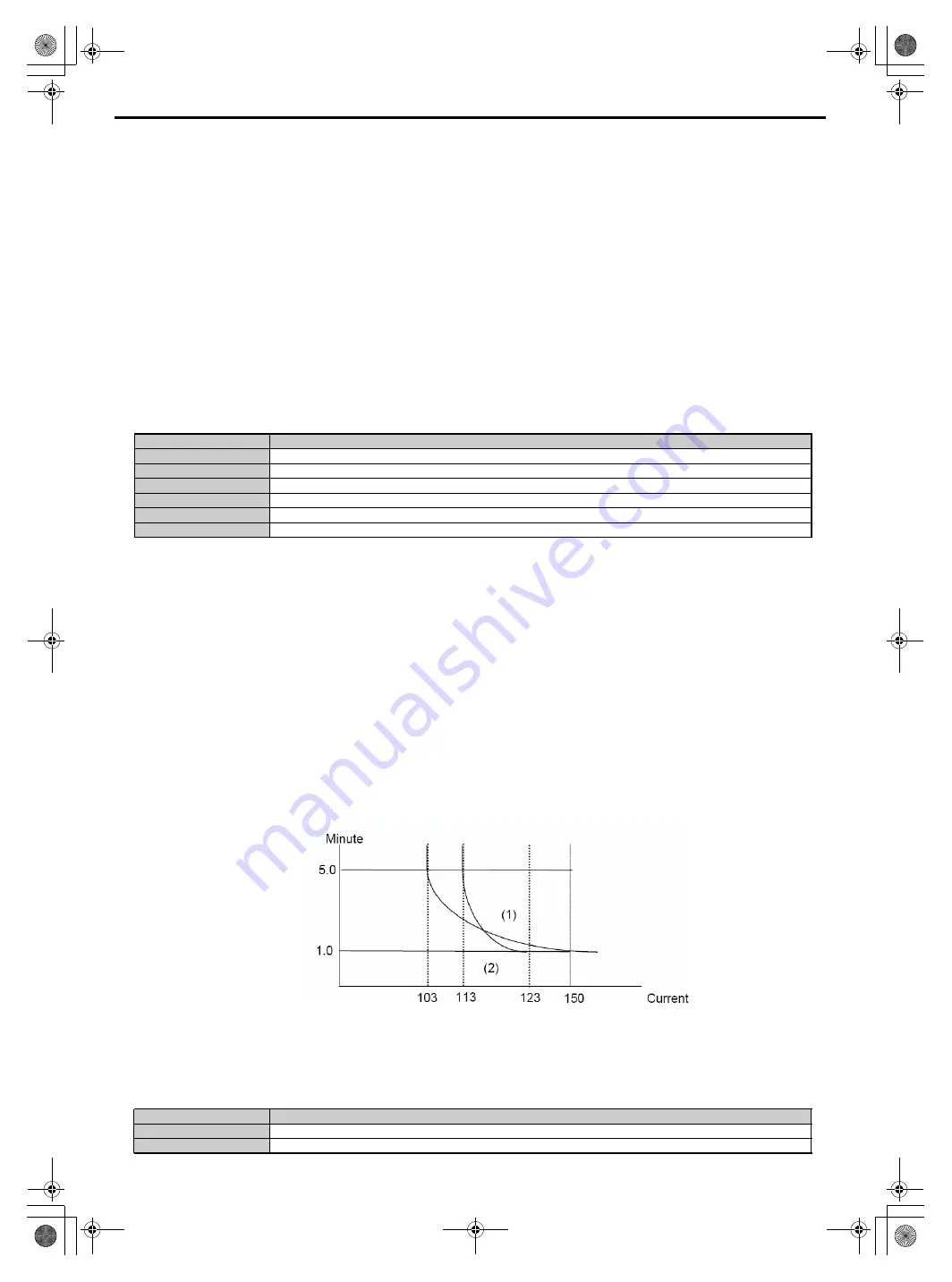
Refer to the following "Motor Overload Protection Time" for the standard motor overload protection curve example
: Setting 08-12 = 0.
■
08-06 Motor Overload Operation Selection
Setting
Description
08-05=0
Dis
abled
08-11=1
Inverter duty
motor
protection
Motor Overload Protection Time
08-05=1
Ena
bled
08-12=0
Constant Torque (OL =103 %) (150 % for 1 Minute)
08-12=1
Variable Torque (OL = 113 %)(123 % for 1 Minute)
08-11=0
Standard Motor protection
Setting
Description
0
Coast-to-Stop After Overload Protection is Activated
1
Drive Will Not Trip when Overload Protection is Activated (OL1)
Setting 08-12 = 0. To protect the general mechanical load, as long as the load is less than 103% rated current, the motor continue to run.
The load is larger than 150% rated current, the motor will run for 1 minute. (Refer to following curve (1)).
The heat sinking function will not be as effective when the motor run at low speed. So the thermal
relay action level will decline at the same time.
(The curve 1 will change to curve 2).
Summary of Contents for e510 series
Page 1: ......
Page 8: ...2 1 Chapter 2 Part Number Definition 2 1 Model Part Number...
Page 13: ...3 4 Screw M4 Screw M4...
Page 34: ...3 25 c Three phase 200V 8 10HP 400V 8 15HP E510 Frame 3 E510 Frame 3 NEMA1...
Page 35: ...3 26 d Three phase 200V 15 20HP 400V 20 25HP E510 Frame 4 E510 Frame 4 NEMA1...
Page 43: ...3 34 3 5 2 Single Three phase Model 200V E510 2P5 H E510 201 H E510 202 H E510 203 H...
Page 197: ......

