4-62
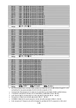
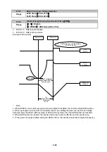
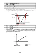
Minute
1.0
150
Current
(2)
(1)
5.0
123
113
103
08- 07
OH Over Heat Protection
Range
【
0
】
:Auto (Depends on heat sink temp.)
【
1
】
:Operate while in RUN mode
【
2
】
:Always Run
【
3
】
:Disabled
¾
08- 07=
【
0
】
:
Cooling fan runs as the inverter detects temperature rise.
¾
08- 07=
【
1
】
:
Cooling fan runs while the inverter is running.
¾
08- 07=
【
2
】
:
Cooling fan runs continuously.
¾
08- 07=
【
3
】
:
Cooling fan is Disabled
.
08- 08
AVR function
Range
【
0
】
:AVR function enable
【
1
】
:AVR function disable
【
2
】
:AVR function disable for stop
【
3
】
:AVR function disable for Deceleration
【
4
】
:AVR function disabled for stop and Deceleration
【
5
】
:when VDC>360/740V
,
AVR function is disabled for stop and Deceleration
¾
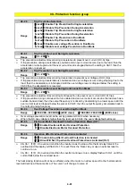
Automatic voltage regulator function provides a level of output voltage stability when there is input
voltage instability. So when
¾
08-08=0, Input voltage fluctuations will not effect the output voltage.
¾
08-08=1. Input voltage fluctuations will cause fluctuations on output voltage.
¾
08-08=2. AVR is disabled during stopping to avoid an increase in stopping time.
¾
08-08=3. AVR is disabled only during deceleration from one speed to another speed. This will avoid
longer than required deceleration time.
¾
08-08=4 AVR function disabled for stop and deceleration.
¾
08-08=5
When VDC>360V(200V class)or VDC>740V(400V class), AVR function is disabled for stop
and deceleration.
08- 09
Input Phase Loss Protection
Range
【
0
】
:Disabled
【
1
】
:Enabled
¾
When
08-09=
【
1
】
:On phase loss warring message PF is
displayed
..
08- 10
Output phase lost protection
Range
【
0
】
:Disabled
【
1
】
:Enabled
¾
When
08-10=
【
1
】
:
On output phase loss ,warning message LF is displayed...
08- 11
Motor type selection:
Range
【
0
】
:
Electronic relays protect standard motor
【
1
】
: Electronic relays protect
inverter duty
motor
08- 12
Motor Overload Protection Curve Selection:
Range
【
0
】
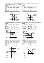
:Constant Torque (OL =103 %) (150 % for 1 Minute)
【
1
】
:Variable Torque (OL = 113 %)(123 % for 1 Minute)
¾
When
08-11
=
【
0
】
:
Set 02-06 as the rated frequency of the motor.
Summary of Contents for e510 series
Page 1: ......
Page 8: ...2 1 Chapter 2 Part Number Definition 2 1 Model Part Number...
Page 13: ...3 4 Screw M4 Screw M4...
Page 34: ...3 25 c Three phase 200V 8 10HP 400V 8 15HP E510 Frame 3 E510 Frame 3 NEMA1...
Page 35: ...3 26 d Three phase 200V 15 20HP 400V 20 25HP E510 Frame 4 E510 Frame 4 NEMA1...
Page 43: ...3 34 3 5 2 Single Three phase Model 200V E510 2P5 H E510 201 H E510 202 H E510 203 H...
Page 197: ......

