


4-18
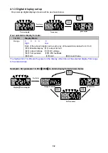
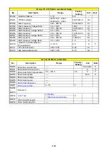
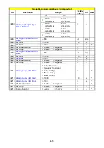
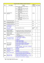
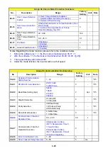
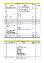
Group 07- Start/Stop Command Setup
No. Description
Range
Factory
Setting
Unit Note
07-00
Momentary Power Loss
and Restart
0: Momentary Power Loss and Restart Disable
1: Momentary Power Loss and Restart Enable
0 -
07-01
Auto Restart Delay
Time
0.0~800.0 0.0
s
07-02
Number of Auto Restart
Attempts
0~10 0
-
07-03
Reset Mode Setting
0: Enable Reset Only when Run Command is Off
1: Enable Reset when Run Command is On or
Off
0 -
07-04
Direct Running on
Power Up
0: Enable Direct run on power up
1: Disable Direct run on power up
1 -
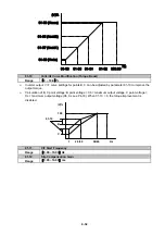
07-05
Delay-ON Timer
1.0~300.0
1.0
S
07-06
DC Injection Brake Start
Frequency (Hz) In Stop
Mode
0.10 ~ 10.00
1.5
Hz
07-07
DC Injection Brake
Level (%) In Stop Mode
0.0 ~ 150.0
50.0
%
07-08
DC Injection Brake
Time (Seconds)
In Stop Mode
0.0 ~ 25.5
0.5
s
07-09
Stopping Method
0: Deceleration to stop
1: Coast to stop
0 -
07-10
Starting Methods
0: Normal Start 1: Speed Search
0
-
07-11
Starting method for auto
restart after fault
0: Speed Search 1: Normal start
0
-
07-12
Power Loss Ride
Through Time
0.0
~
2.0
0.5 s
07-13
Main Circuit Low
Voltage Detection Level
150.0
~
210.0 300.0
~
420.0
190.0/3
80.0
Vac
07-14
Kinetic Energy Back-up
Deceleration Time
0.0~25.0: KEB Deceleration Time
0.0
s
Summary of Contents for e510 series
Page 1: ......
Page 8: ...2 1 Chapter 2 Part Number Definition 2 1 Model Part Number...
Page 13: ...3 4 Screw M4 Screw M4...
Page 34: ...3 25 c Three phase 200V 8 10HP 400V 8 15HP E510 Frame 3 E510 Frame 3 NEMA1...
Page 35: ...3 26 d Three phase 200V 15 20HP 400V 20 25HP E510 Frame 4 E510 Frame 4 NEMA1...
Page 43: ...3 34 3 5 2 Single Three phase Model 200V E510 2P5 H E510 201 H E510 202 H E510 203 H...
Page 197: ......