4- 86
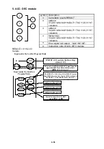
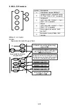
5. ACC- DEC module
symbol Description
c
Calculation results RESULT
d
addend
V1(AS1~AS4,MD1~MD4,T1~T8,C1~C8,V1~V7,
constant)
e
addend
V2(AS1~AS4,MD1~MD4,T1~T8,C1~C8,V1~V7,
constant)
f
filamentous
V3(AS1~AS4,MD1~MD4,T1~T8,C1~C8,V1~V7,
constant)
g
Error signal coil output
(
NOP /
M1~MF
)
h
Instruction code of ACC- DEC module
RESULT= V1+V2-V3
Sample:
I1
(AS1)
(
Q1
)
ON/OFF of I1 controls the Run /Stop
status of AS1
5702
6553
4536
5387
AS1
M1
M1 is coil error
,
if the RESULT is more than the
upper limit(65535) or Below the lower limit
(
0
)
,M1 is ON,Q1is ON
Input under the Function
Program Mode
Input under the Ladder Program Mode
The RESULT of AS1(Note:if the RESULT is more
than 65535,Here can only display 65535;similarly,if
the RESULT is less than the lower limit of 0 )
Addend value of V1
Addend value of V2
Addend value of V3
Instruction code of ACC- DEC
module
(
AS1~AS4
)
(
M1
)
5
6
2
1
3
4
Summary of Contents for e510 series
Page 1: ......
Page 8: ...2 1 Chapter 2 Part Number Definition 2 1 Model Part Number...
Page 13: ...3 4 Screw M4 Screw M4...
Page 34: ...3 25 c Three phase 200V 8 10HP 400V 8 15HP E510 Frame 3 E510 Frame 3 NEMA1...
Page 35: ...3 26 d Three phase 200V 15 20HP 400V 20 25HP E510 Frame 4 E510 Frame 4 NEMA1...
Page 43: ...3 34 3 5 2 Single Three phase Model 200V E510 2P5 H E510 201 H E510 202 H E510 203 H...
Page 197: ......


