


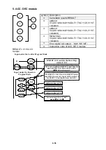
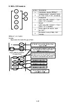


5-6
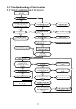
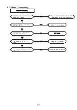
5.3
Troubleshooting of the Inverter
5.3.1
Quick troubleshooting of the Inverter
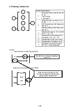
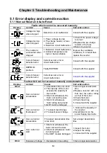
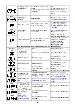
INV Fault
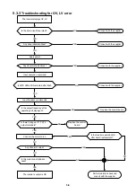
Visually check controller
and Drive boards
*to next page
Check burnt and
damaged parts
Consult with the supplier
Replace fuse
Consult with the supplier
Consult with the supplier
Check according to
displayed fault messages
Replace the pre-charge
resistor
Check terminals and
wiring
Consult with the supplier
Perform detailed check and
consult with the supplier
Is fault known?
Symptoms other than burn
out, damage, or fuse
meltdown in the inverter?
Any Symptoms of burn
out and damage?
Is the main circuit DM
intact?
Fault signal?
Is the fuse intact
?
Is the main circuit
I.G.B.T intact?
Any visual
abnormalities?
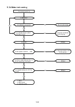
Are displays and
indicators of the
operating unit working
normally?
Is +5V control voltage
correct?
Is the DC input voltage
controlling the power
correct
Any fault display?
What the message
?
Is LED lit?
Replace control board
and digital operating unit
Is the error eliminated
after replacing control
board?
YES
NO
NO
YES
NO
NO
NO
YES
YES
YES
YES
NO
NO
NO
YES
YES
YES
YES
NO
NO
YES
NO
YES
NO
YES
NO
YES
NO
Apply the power
Summary of Contents for e510 series
Page 1: ......
Page 8: ...2 1 Chapter 2 Part Number Definition 2 1 Model Part Number...
Page 13: ...3 4 Screw M4 Screw M4...
Page 34: ...3 25 c Three phase 200V 8 10HP 400V 8 15HP E510 Frame 3 E510 Frame 3 NEMA1...
Page 35: ...3 26 d Three phase 200V 15 20HP 400V 20 25HP E510 Frame 4 E510 Frame 4 NEMA1...
Page 43: ...3 34 3 5 2 Single Three phase Model 200V E510 2P5 H E510 201 H E510 202 H E510 203 H...
Page 197: ......