5-1
Chapter 5 Troubleshooting and Maintenance
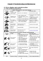
5.1 Error display and corrective action
5.1.1 Manual Reset and Auto-Reset
Faults which can not be recovered manually
Display content
Cause
Corrective
action
-OV-
Voltage too high
when stopped
Detection circuit malfunction
Consult with the supplier
-LV-
Voltage too low
when stopped
1. Power voltage too low
2. Pre-charge resistor or fuse
burnt out.
3. Detection circuit malfunction
1.Check if the power voltage
is correct
2.Replace the pre-charge
resistor or the fuse
3.Return the inverter
-OH-
The inverter is
overheated when
stopped
1. Detection circuit malfunction
2. Ambient temperature too
high or bad ventilation
Improve the ventilation
conditions, if no result then
replace the inverter
EPr
Current Sensor
detection error
Current sensor error or
circuit malfunction
Consult with the supplier
COt
EEPROM
problem
Faulty EEPROM
Consult with the supplier
CtEr
Current Sensor
detection error
Current sensor error or
circuit malfunction
Consult with the supplier
Faults which can be recovered manually and automatically
Display content
Cause
Corrective
action
OC-A
Over-current at
acceleration
1.Acceleration time too short
2.The capacity of the motor
exceeds the capacity of
the inverter
3.Short circuit between the
motor coil and the case
4.Short circuit between
motor wiring and ground
5.IGBT module damaged
1.Set a longer acceleration
time
2.Replace inverter with one
that has the same rating
as that of the motor
3.Check the motor
4.Check the wiring
5. Consult with the supplier
OC-C
Over-current at
fixed speed
1.
Transient load change
2.
Transient power change
1. Increase the capacity of
the inverter
2.Install inductor on the
power Supply input side
OC-d
Over-current at
deceleration
The preset deceleration time
is too short.
Set a longer deceleration
time
OC-S
Over current at
start
1.Short circuit between the
motor coil and the case
2.Short circuit between motor
coil and ground
3.the IGBT module damaged
1.Inspect the motor
2.Inspect the wiring
3. Consult with the supplier
OV-C
Excessive Voltage 1.Deceleration time setting
1.Set a longer deceleration
Summary of Contents for e510 series
Page 1: ......
Page 8: ...2 1 Chapter 2 Part Number Definition 2 1 Model Part Number...
Page 13: ...3 4 Screw M4 Screw M4...
Page 34: ...3 25 c Three phase 200V 8 10HP 400V 8 15HP E510 Frame 3 E510 Frame 3 NEMA1...
Page 35: ...3 26 d Three phase 200V 15 20HP 400V 20 25HP E510 Frame 4 E510 Frame 4 NEMA1...
Page 43: ...3 34 3 5 2 Single Three phase Model 200V E510 2P5 H E510 201 H E510 202 H E510 203 H...
Page 197: ......

