RUN EXCITE-2008: Service & Maintenance Manual - rev. 1.3
Page 7.29
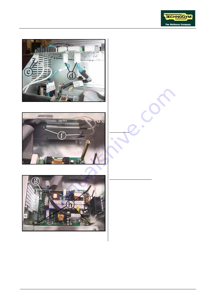
Figure 7.17-4
4.
Unplug the two cables
(d)
coming from the
AT power supply board.
5.
Unplug the faston
(e)
of the two cables
coming from the resistance.
6.
Remove the AT UL driver board.
Figure 7.17-5
Resistance:
1.
Unscrew the two screw
(f)
using a Phillips
screwdriver.
2.
Remove the resistance.
Figure 7.17-6
AT power supply board:
1.
Unplug the cable coming from the fan.
2.
Unscrew the screw
(g)
using a Phillips
screwdriver.
3.
Unscrew the spacer
(h)
using a 7mm wrench.
4.
Remove the board.
To reassemble the electronics boards, carry out
the above steps in reverse order.
Summary of Contents for EXCITE Run 500
Page 1: ...D446 D448 D449 SERVICE MAINTENANCE MANUAL REV 1 3...
Page 2: ......
Page 4: ......
Page 32: ...RUN EXCITE 2008 Service Maintenance Manual rev 1 3 Page 2 20 Page intentionally left blank...
Page 52: ...RUN EXCITE 2008 Service Maintenance Manual rev 1 3 Page 3 20 Page intentionally left blank...
Page 59: ...RUN EXCITE 2008 Service Maintenance Manual rev 1 3 Page 4 7 Page intentionally left blank...
Page 60: ......
Page 127: ...RUN EXCITE 2008 Service Maintenance Manual rev 1 3 Page 7 19 Continued on following page...
Page 148: ......
Page 217: ...RUN EXCITE 2008 Service Maintenance Manual rev 1 3 Page 9 63 Page intentionally left blank...
Page 218: ......
Page 229: ...RUN EXCITE 2008 Service Maintenance Manual rev 1 3 Page 11 7 Page intentionally left blank...
Page 230: ......
Page 233: ......


