background image

5-16

P

ROTEGÉ

® 616 I

NSTALLATION AND

M

AINTENANCE

M

ANUAL

,  F

EBRUARY

2001

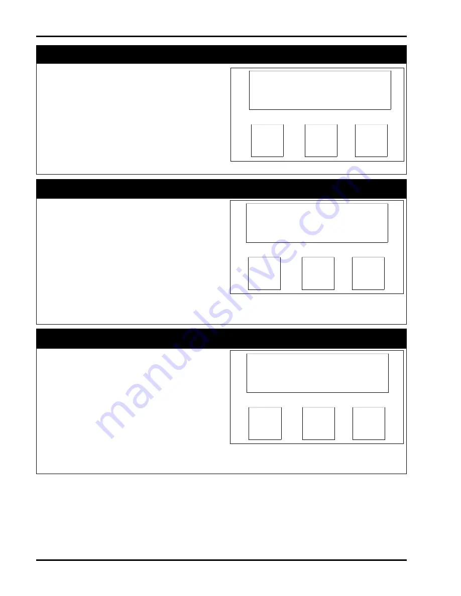
11.3 - Call Handling

- To view Call Handling

programming, press the F3 key "Show.”

F1

F2

F3

3. CALL HANDLING

back

next

show

Category 3 - Call Handling

Figure 5-30: Call Handling Screen

11.3.1 - Call Handling - Intrusion

- Intrusion, if per-

mitted, allows a party to join a call on a CO line
occupied by an extension with the same or a lower
Class of Service. The setting of "Y” permits intrusion
on a line and extension basis. To disable intrusion
from any extension, press the F3 softkey, "Chg,” and
toggle to "N.”

A party who intrudes on a call may talk with
all people on the line.

If enabled an intrusion tone will be heard by
the extension.

Default: 

System intrusion is disabled.

F1

F2

F3

INTRUSION: N

back

next

chg

Category 3 - Call Handling - Intrusion

Figure 5-31: Intrusion Screen

11.3.2 - Call Handling - Intrusion Tone 

- The intru-

sion tone, when enabled, alerts the extension user
that another party is entering into the conversation.
The setting of "Y” enables the intrusion tone. To dis-
able the tone, press the F3 softkey, "Chg,” and toggle
to "N.”

Default: 

The intrusion tone is enabled.

F1

F2

F3

INTRUS. TONE: Y

back

next

chg

Category 3 - Call Handling - Intrusion Tone

Figure 5-32: Intrusion Tone Screen

Summary of Contents for Protege 616

Page 1: ...Proteg 616 Installation and Maintenance Manual 699066 Version 3 0...

Page 2: ...Copyright 2000 Sprint Products Group Inc All Rights Reserved...

Page 3: ...al Equipment 2 4 6 1 Music on Hold Background Music 2 4 6 2 Voice Mail 2 4 6 3 Fax 2 4 6 4 External Paging 2 4 6 5 Power Failure Transfer 2 4 7 Station Instruments 2 4 7 1 Common Keyset Features 2 5 7...

Page 4: ...ecall 4 5 1 35 Ringing Line Preference 4 5 1 36 Soft Key 4 5 1 37 Speed Dialing System 4 6 1 38 Station Group Assignment 4 6 1 39 Station Numbering Plan 4 6 1 40 System Time 4 6 1 41 Toll Restriction...

Page 5: ...11 11 1 8 Function Key Allow 5 11 11 1 9 System Speed Check 5 12 11 1 10 ICM Mode 5 12 11 2 Category 2 Trunkline 5 13 11 2 1 Voice Mail Group Answer 5 13 11 2 2 Dialing 5 13 11 2 3 Call Abandon 5 14...

Page 6: ...vice 5 8 5 7 Line Assignment Screen 5 9 5 8 Individual Line Assignment Screen 5 9 5 9 Receive Assignment Screen 5 9 5 10 Individual Receive Assignment Screen 5 9 5 11 Ring Assignment Screen 5 10 5 12...

Page 7: ...Digit Screen 5 31 5 93 Extension Class Of Service Screen 5 32 5 94 Extension Day Allowed COS Screen 5 32 5 95 Extension Night Allowed COS Screen 5 32 5 96 Extension COS Screen 5 32 5 97 Extension COS...

Page 8: ...or table The product may fall causing serious damage to the product 6 Slots and openings in the KSU are provided for ventilation to protect it from overheating These openings must not be blocked or co...

Page 9: ...abel of this equip ment If requested this information must be pro vided to the telephone company The following information must be provided to the telephone company if requested USOC RJ25C Service Ord...

Page 10: ...LOAD NUMBER LN assigned to each terminal device denotes the percentage of the total load to be connected to a telephone loop which is used by the device to prevent overloading The termination on a lo...

Page 11: ...ns Equipment requiring servicing should be returned to place of purchase whenever possible Otherwise call 1 800 791 1110 to request a Material Return Authorization MRA number and obtain return instruc...

Page 12: ...x PROTEG 616 INSTALLATION AND MAINTENANCE MANUAL FEBRUARY 2001 This page left blank intentionally...

Page 13: ...tal extensions by installation of an optional 3x8 expan sion board Each digital extension port can be modi fied with the use of an Analog Adapter to provide two analog ports The maximum number of anal...

Page 14: ...clude call abandon class of service distinctive ring power failure transfer pri vate line toll restriction and many more A complete listing of features can be found in chapter 4 Fea tures of this manu...

Page 15: ...ects current Sprint Products Group standards Its contents are subject to change without notice While every effort has been made to avoid errors Sprint Products Group disclaims any liability arising fr...

Page 16: ...1 4 PROTEG 616 INSTALLATION AND MAINTENANCE MANUAL FEBRUARY 2001 This page left blank intentionally...

Page 17: ...tem Resource Capacity Table 2 1 offers a listing of the system resource capacities for such resources as Speed Dial numbers conferencing and pre programmed messages 2 1 PROTEG 616 INSTALLATION AND MAI...

Page 18: ...50 block already terminated Alternatively the cable can be prepared on site Instructions on preparing this cable are not included in this manual 2 4 Grounding Cables Sprint Products Group highly reco...

Page 19: ...before the AC adapter is plugged into the AC outlet 4 Internal Components 4 1 3x8 Interface Board 3x8 Expansion Board The main PCB also known as Motherboard consists of the following circuits Eight di...

Page 20: ...c sources are subject to copyright restriction 6 2 Voice Mail Commercial voice mail systems can be attached to an analog adapter port The interface requirements for a voice mail system are the same as...

Page 21: ...ess other extensions 7 2 Business Keyset with Display The Business 15DCL Keyset with Display is a 26 but ton phone that has 16 programmable feature keys 15 of which have dual color LEDs The Business w...

Page 22: ...2 6 PROTEG 616 INSTALLATION AND MAINTENANCE MANUAL FEBRUARY 2001 This page left blank intentionally...

Page 23: ...G wire is recom mended Station cabling is terminated on the 66M1 50 block at the MDF and four conductor modular jacks at the station 8 CO Line Cabling Terminate the CO lines on the 66M1 50 block at th...

Page 24: ...rk interface 4 Use caution when installing or modifying tele phone lines 1 7 Tools and Supplies A basic list of tools and supplies required to install the Proteg 616 system is provided in the Tools an...

Page 25: ...minating station wiring CO lines and KSU connector For details on 66M1 50 block connections see Station Cabling in this chapter 2 Installation 2 1 Unpack and Inspect Cabinet 1 Remove the KSU cabinet f...

Page 26: ...EPROM from its carrier 5 Insert the EPROM in its socket Align the notch on the chip with the notch on the socket Make sure that all pins are properly seated 6 Replace the KSU cover and the four screws...

Page 27: ...SU cover and secure with the four cover screws 2 4 Install KSU The KSU can be mounted on a wall by attaching it to the 3 4 inch wooden backboard used for the MDF See the section on Install MDF discuss...

Page 28: ...Red Orange Station Port 7 33 8 Red Green Station Port 8 34 9 Red Brown N C 35 10 Red Slate N C 36 11 Black Blue N C 37 12 Black Orange N C 38 13 Black Green N C 39 14 Black Brown N C 40 15 Black Slat...

Page 29: ...e run the cables across them at right angles 3 Do not run station cables inside electrical conduit already occupied by AC power cable To do so is a violation of the National Electrical Code 4 Do not r...

Page 30: ...increase the resistance of a cable which reduces the allow able cable run length Repeat this test for each station cable Install bridging clips on the station blocks to complete the cable resistance...

Page 31: ...ee end of the coiled handset cord into the jack on the handset Place the handset in its cradle 7 Plug the free end of the gray line cord into the wall mounted modular jack 3 3 Wall Mounting 1 Lift the...

Page 32: ...peripheral equipment Such equipment may include external paging systems and music on hold devices 5 System Initialization When the installation steps explained in this chapter have been completed the...

Page 33: ...mode night replaces extension name 1 2 Alternate Answering Position Overflow Attendant DATABASE PROGRAMMING 4 RESOURCE ALTERNATE A single extension can be programmed as the alter nate attendant The al...

Page 34: ...NOTES If the alert tone is enabled the extension receiving the intercom call will hear an alert when the Barge In occurs Once the Barge In occurs the callers are on a conference call Only one Barge In...

Page 35: ...ng links provided by the system NOTES Any incoming intercom call can reach any sta tion when the extension is on hook 1 14 Discriminating Ringing DATABASE PROGRAMMING NONE Incoming line ring camp on l...

Page 36: ...ll be occupied Proteg 616 provides two line groups 1 24 Line Interface DATABASE PROGRAMMING NONE Proteg 616 can access only Loop Start lines in which loop current is used to determine if the call is s...

Page 37: ...Line DATABASE PROGRAMMING 2 TRUNKLINE PRIVATE TO Extensions may be assigned an exclusive line to use and no other extension can access that line Incoming or held calls on this private line cannot be a...

Page 38: ...ystem Time DATABASE PROGRAMMING NONE The system uses a timer IC for reference for such functions as the system service mode change and reminder clock functions NOTES The system clock detects leap year...

Page 39: ...PROGRAMMING 6 CONTROL VOICE MAIL The Proteg 616 provides basic voice mail integra tion Analog extensions can be assigned to a voice mail hunt group Calls to the voice mail group will hunt from the fi...

Page 40: ...Hold will be solid red when the feature is enabled 2 4 Automatic Line Selection FUNCTION 95 ON FUNCTION 95 OFF The system automatically chooses an ICM link any idle line specific prime line or idle li...

Page 41: ...e is not answered within the programmed recall time the call reverts to the originator If the originator does not answer within 30 seconds the call rings to the attendant If the attendant does not ans...

Page 42: ...total of up to eight 8 simultaneous conferences The conference controller has the option to force individ ual parties out of the conference to add individual parties when others drop out or have a pr...

Page 43: ...he FLASH key if programmed or its access code can be pressed to generate a loop break duration on the line call in order to request some features or ser vices which are provided by CENTREX or Central...

Page 44: ...idual line key i e line status will be indicated on both line group and indi vidual line key 4 The lamp indication on both the line group and individual key are treated in the same way When all lines...

Page 45: ...cate the times to switch between day and night mode If in Time mode and the system is manually changed to night mode then Time mode will have to be reenabled to have the system follow the Time mode 2...

Page 46: ...nsferred party 2 Line Call If the extension does not answer the transferred call within a certain programmed period it will recall to the original extension Calls may also be transferred to the voice...

Page 47: ...on users may control the volume level for ringer speaker and handset respectively at their dis cretion The desired level is stored in the system for future calls 4 15 PROTEG 616 INSTALLATION AND MAINT...

Page 48: ...4 16 PROTEG 616 INSTALLATION AND MAINTENANCE MANUAL FEBRUARY 2001 This page left blank intentionally...

Page 49: ...ent Termination may also occur by destruction of all media included in this package Warranty This software is provided as is with out warranty of any kind either expressed or implied including but not...

Page 50: ...the system pressing CHG will erase the cur rent information For fields that accept Null as a valid entry press SAVE when the field is blank NEXT Press the NEXT softkey to go to the next programming it...

Page 51: ...AL FEBRUARY 2001 Table 5 1 Database Features Programming Categories The table shows the six programming categories and the features that can be pro grammed in each of these categories 1 Extension Show...

Page 52: ...ive transfer and access lines in a specific group 9 2 6 Private To permits a line to be assigned for use by the specified extension only 9 2 7 ICLID determines if the system monitors the line for call...

Page 53: ...strictions if any that are placed on extensions for each COS 9 6 Control Category 6 This category contains programming information for voice mail operation and the method to perform either a Warm or C...

Page 54: ...utes 0 Abandon Time 50 1500 ms 600 CO Flash 0 1 3 0 seconds 0 7 Remind Time 0 90 seconds 30 Pause Time 1 5 5 0 seconds 1 5 PBX Code 0 9 or 00 99 9 PBX Auto Pause 1 9 seconds 2 Tone Time 70 120 ms 70 V...

Page 55: ...place 5 7 PROTEG 616 INSTALLATION AND MAINTENANCE MANUAL FEBRUARY 2001 Resource cont d Line Copy Any line None Extension Copy Any extension None Dial Wait Time 0 8 seconds 1 KSU Revision N A N A Feat...

Page 56: ...extension first By using the softkeys Day and Night COS can be changed For this system the class of service of 0 restricts none of the associated features from this extension These features include t...

Page 57: ...d when the Line Assignment is updated Default All lines are accessible to all extensions F1 F2 F3 LINE ASSIGNMENT back next show F1 F2 F3 LINE 1 Y back next show Category 1 Extension Flexible Line Ass...

Page 58: ...sions ring when incoming line calls are signaling In Night mode only extension 10 rings when incoming line calls are signaling F1 F2 F3 RING ASSIGNMENT back next show F1 F2 F3 LINE 1 Y back next show...

Page 59: ...from 58 to 65 F1 F2 F3 EXT POSITION 10 back next chg Category 1 Extension Extension Position Figure 5 17 Extension Position Screen 11 1 8 Extension Function Key Allow To permit or prohibit the use of...

Page 60: ...en 11 1 10 Extension ICM Mode There are two set tings for the ICM Mode ring and page If set to ring when an intercom call is placed to an extension the extension will always ring to alert the user to...

Page 61: ...between the four choices This programming overrides Extension Ring Assignment and Trunkline Private To programming when the Voice Mail Group Answer is active Note Activating Voice Mail Answer Group do...

Page 62: ...toggle between the four choices Most lines will be assigned as CO type If the 616 is connected behind a PBX system or using CENTREX then the lines will be marked as PBX type Note Don t forget to desi...

Page 63: ...ignation is removed the line will be accessible to all extensions that belong to the same extension group as the spe cific extension Default No lines are assigned to Private To F1 F2 F3 PRIVATE TO NUL...

Page 64: ...press the F3 softkey Chg and toggle to N A party who intrudes on a call may talk with all people on the line If enabled an intrusion tone will be heard by the extension Default System intrusion is di...

Page 65: ...all Handling Abandon Time Establishes the minimum duration of open that the Central Office must produce for the system to recognize dis connect supervision The timer range is 50 to 1500ms Default Aban...

Page 66: ...5 2 0 3 5 5 0 seconds Default The pause time is 1 5 seconds F1 F2 F3 PAUSE TIME 1 5 back next chg Category 3 Call Handling Pause Time Figure 5 37 Pause Time Screen 11 3 8 Call Handling PBX Code This f...

Page 67: ...is sending to the central office To change the time press F3 softkey Chg and enter the number of milliseconds desired The range of valid entries is 70 90 120 milliseconds Default The tone signal is 70...

Page 68: ...o a voice mail port The range of valid entries is 60 90 120 150 milliseconds programmable in 30 millisecond increments To change the value press the F3 soft key Chg and enter the valid entry Default T...

Page 69: ...Call Handling SLT Hookflash Figure 5 46 SLT Hookflash Screen F1 F2 F3 START 200 back next chg Figure 5 47 SLT Hookflash Start Screen The Start field determines the minimum valid hookflash duration fo...

Page 70: ...o 9 then the PBX code has to be 0 Default The access code is 0 F1 F2 F3 OPERATOR CODE 0 back next chg Category 3 Call Handling Operator Code Figure 5 49 Operator Code Screen 11 3 16 Call Handling Dial...

Page 71: ...and press the F2 softkey Press the F3 softkey Chg to enter the year date hour or minute After the field is cleared the F2 softkey assumes the function of a Save key Enter the new date and press the F2...

Page 72: ...ice for dash three times for ampersand and four times for 1 Default The user name is empty F1 F2 F3 USER NAMES back next show Category 4 Resource User Names Figure 5 59 User Names Screen F1 F2 F3 EXT...

Page 73: ...e F2 softkey Next until the correct day is displayed Once the day is correct press the F3 softkey Show For each day the Start and End times must be programmed Use the F3 softkey Chg to enter the time...

Page 74: ...F3 softkey Chg and use the dialpad to enter a 16 character message Press the key to move the cursor one space Use the 0 key to enter the letters Q Z period and the numeral 0 Press 0 once for Q twice f...

Page 75: ...ber to which the new speed dial number is being chained The 616 treats the chaining command Flnn as three digits Note that when Function 1 is entered the 616 displays it as Default All system speed di...

Page 76: ...g database parameters day COS night COS line assignment receive assignment ring assignment extension group function key allow system speed check and intercom mode Default There is no programming F1 F2...

Page 77: ...r of a previously pro grammed keyset and press the F2 softkey Save Enter the number of the extension to copy the fea tures to and press the F2 softkey Save Note This programming can rearrange the line...

Page 78: ...ain to program the Digit Interval Table 11 5 Restriction To program Toll Restriction programming press the F3 softkey Show F1 F2 F3 5 RESTRICTION back next show F1 F2 F3 DIALING TABLE back next show C...

Page 79: ...a number up to 10 digits in length The following are tips for programming the Start and End Digit Strings To allow one specific number or range the same number must be programmed in the both the Start...

Page 80: ...ight Class of Services must be programmed Press the F3 softkey Show to view each of the eight classes of service To enable each class of service to use each interval press the F3 softkey Chg to toggle...

Page 81: ...or example if the voice mail ports are 13 and 14 then their corresponding B2 channels 61 and 62 also should be programmed The system supports eight Voice Mail Hunt Group Members Enter the port numbers...

Page 82: ...F1 F2 F3 PREFIX CODE back next show Category 6 Control Voice Mail Figure 5 102 Voice Mail Prefix Code F1 F2 F3 ICM VM 12 back next chg F1 F2 F3 TRANSFER 11 back next chg F1 F2 F3 BUSY FWD 11 back next...

Page 83: ...stem needs to be reset but the customized programming needs to remain Press the F3 softkey Chg to continue with the warm start Before the system will reset itself the system prompts to determine if th...

Page 84: ...rt the cold start press the F1 softkey No Note All call processing will immediately cease F1 F2 F3 SYS COLD START bksp next show Category 6 Control System Cold Start Figure 5 113 System Cold Start Scr...

Page 85: ...the KSU and place it on a solid surface Remove the four screws from the cover 2 Connect the grounding wrist strap to an approved ground 3 Find the anti static bag containing the EPROM chip for the Co...

Page 86: ...ssed To Answer ICM Or Incoming Call Users cannot pick up the handset to answer an incoming or intercom call The flashing LED must be pressed The Automatic Line Selection is set to ICM with Voice Call...

Page 87: ...Conversion 4 10 Dial Wait Time 5 4 5 22 Dialing 5 13 Dialing Table 5 5 5 30 Dialing Table DGT Interval 5 31 Dialing Table Extension COS 5 32 Dialing Type Selection 4 3 5 4 Direct Pick Up 4 8 Direct St...

Page 88: ...User Feature Keys 4 13 R Rebooting the System 5 2 Recall 4 5 Recall Time 5 4 5 20 Receive Assignment 5 4 Release 4 13 Resource category 5 23 Restriction category 5 30 Remind Time 5 4 5 18 Ring Assign...

Reviews: