1-37
DSR-80/80P/60/60P
72
Chapter 6
Maintenance and Troubleshooting
Chapter 6
Maintenance and Troubleshooting
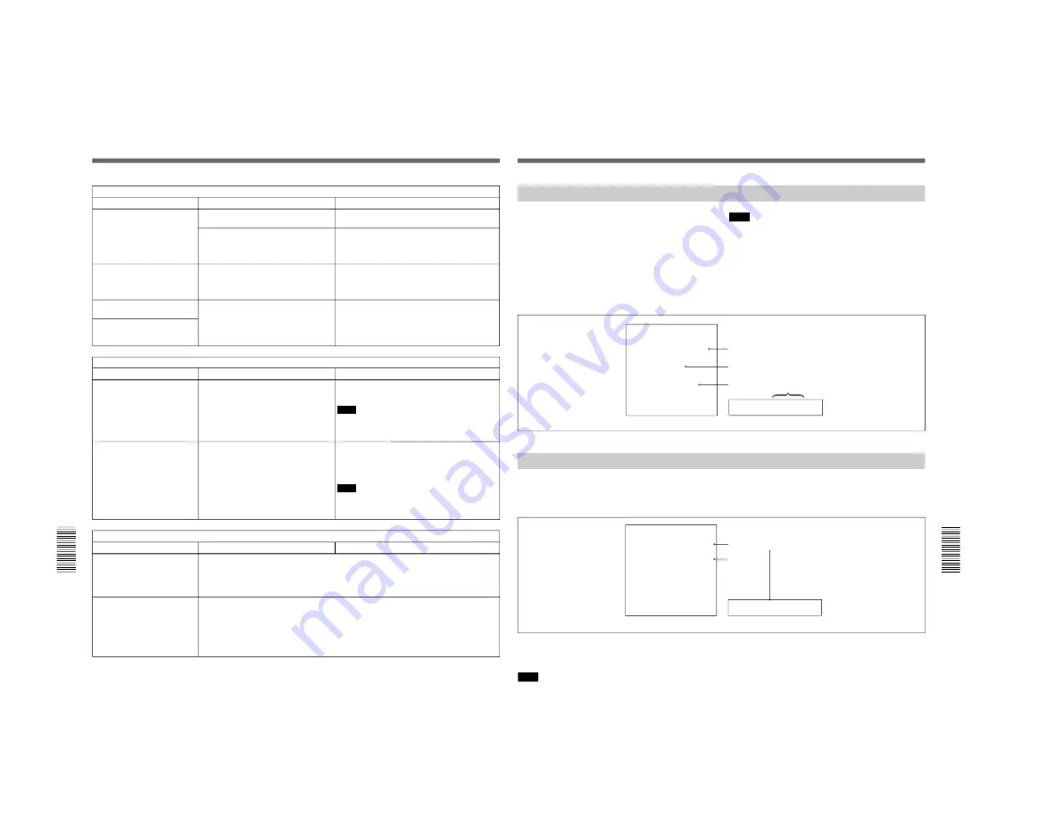
Monitor problems
Symptom
Cause
Remedy
Troubleshooting
Data is not superimposed on
the monitor screen.
“CHARA. DISPLAY” under the DISPLAY
CONTROL menu item is set to “OFF”.
Set “CHARA. DISPLAY” to “ON”.
(See page 43.)
The image on the monitor’s
screen is too bright.
The 75
Ω
termination switch for video
input on the monitor is in the OFF
position or a 75
Ω
terminator is not fitted
to its video input connector.
Set the 75
Ω
termination switch to ON or connect
a terminator.
The monitor is not connected to the
VIDEO OUT 2 (SUPER) connector of
this unit.
Connect the monitor to the VIDEO OUT 2
(SUPER) connector. (You must make this
connection to display any type of text on the
monitor.)
The image on the monitor’s
screen is too dark.
In a video signal loop-through connection
of video monitors, 75
Ω
termination
switches for video input on monitors
other than the loop-end monitor are in
the ON position.
Set the 75
Ω
termination switches to OFF on all
monitors other than the loop-end monitor .
The image is too dark when
recording a composite video
signal.
Audio problems
Symptom
Cause
Remedy
When an AES/EBU, SDI or
QSDI digital audio input is
selected, the AUDIO INPUT
LEVEL control konbs do not
work.
“DIGITAL INPUT” under the AUDIO
CONTROL menu item is set to
“BYPASS”.
Set “DIGITAL INPUT” to “VARIABLE”.
(See page
47.)
Note
To be able to perform this operation, it is
necessary to set the menu item “MENU GRADE”
to “ENHANCED”.
(See page 47.)
When a QSDI signal from a
player VCR is selected as the
input to this unit, putting the
player into jog mode stops this
unit from outputting an EE
audio signal.
“QSDI AUDIO MON” under the
OPERATIONAL FUNCTION menu item
is set to “QSDI”.
Change the menu setting of “QSDI AUDIO MON”
to a setting other than “QSDI”, and input an audio
signal corresponding to the new setting.
(See
page 43.)
Note
To be able to perform this operation, it is
necessary to set the menu item “MENU GRADE”
to “ENHANCED”.
(See page 47.)
Editing problems
Symptom
Cause
Remedy
Execution of video editing in
insert mode causes subcode
data recorded on tape other
than time code data to
disappear from tape.
This phenomenon cannot be avoided with an editing system
using this unit as the recorder.
During audio editing in insert
mode, a strange image
appears on the video monitor
screen like a partial frozen
image of a frame immediately
before the IN point being mixed
in the playback picture.
This phenomenon cannot be avoided with an editing system
using this unit as the recorder, but editing itself will be achieved
exactly as you have designed.
Chapter 6
Maintenance and Troubleshooting
73
Chapter 6
Maintenance and Troubleshooting
Error Messages
This unit is provided with a self-diagnostic function
that detects internal abnormalities. When it detects an
abnormality, it outputs an error message to the monitor
screen and indicates an error code in the time counter
display.
If an error message appears, follow the direction
indicated under the message in the monitor screen.
Note
To display error messages on the monitor screen, it is
necessary for the monitor to be connected to the
VIDEO OUT 2 (SUPER) connector, and for
“CHARA. DISPLAY” under the DISPLAY
CONTROL menu item to be set to “ON” (factory
default setting).
For details of menu settings, see Chapter 4.
Alarm Messages
Error message
Error02-603
ERROR
AN ERROR HAS BEEN
DETECTED. INFORM SERVICE
OF FOLLOWING CODE:
02-603
PRESS EJECT KEY
TO EJECT TAPE.
Error code
Direction
Error code
Monitor screen
Time counter display
such as the ones shown below to the monitor screen
and the time counter display.
When a setting, connection or operation error has been
made, or when a problem such as condensation on
heads has occurred, the unit outputs alarm messages
REMOTE!
ALARM
REMOTE MODE IS SELECTED
SET REMOTE/LOCAL SWITCH
TO LOCAL
Monitor screen
Time counter display
Direction
Cause of alarm
If an alarm message appears, follow the direction
indicated under the message in the monitor screen.
Note
To display alarm messages on the monitor screen, it is
necessary for the monitor to be connected to the
VIDEO OUT 2 (SUPER) connector, and for
“CHARA. DISPLAY” and “ALARM” under the
DISPLAY CONTROL menu item to be set to “ON”
(factory default setting) and “REF. ALARM” to be set
to“ON” or “ON (LIMITED)” (factory default setting).
For details of menu settings, see Chapter 4.
Summary of Contents for DVCAM DSR-60
Page 2: ......
Page 54: ......
Page 174: ......
Page 220: ......
Page 236: ......
Page 238: ...8 2 N DSR 80 80P 60 60P SY 241B 241 CV101 CHARA SIZE 10 1 N DSR 60 80 ...
Page 242: ...8 2 P DSR 80 80P 60 60P SY 241B 241 CV101 CHARA SIZE 10 1 P DSR 60P 80P ...
Page 284: ......


