1-18
DSR-80/80P/60/60P
Setting the Time Data
Chapter 3 Convenient Functions for Editing Operation
34
Chapter 3
Convenient Functions for Editing Operation
7
Press the SET (YES) button.
The message “NOW SAVING...” appears on the
monitor screen, “Saving...” appears in the time
counter display, and the new settings are stored in
the unit’s memory.
After this saving operation is completed, the
monitor screen and the time counter display return
to their usual status.
Note
The set data may be lost if you power off the unit
while the above saving operation is in progress.
Wait until the saving operation is completed before
powering off.
Advancement of internal time code
generator
The internal time code generator can advance in either
of two modes, which can be set via “RUN MODE”
under the TIME CODE menu item.
FREE RUN : Advancement starts when the data
saving operation is completed.
REC RUN : Advancement starts when recording
starts and stops when recording stops.
To set the current time as the time code’s
initial value
In Step
2
above, set “RUN MODE” under the TIME
CODE menu item to “FREE RUN”, then set the
current time (format: HH:MM:SS:FF = hours:
minutes:seconds:frame number) in Step
3
and
subsequent steps.
Synchronizing Internal and
External Time Codes
When the unit is equipped with an optional DSBK-
130/130P Time Code Input/Output Board, the internal
time code generator can be locked to (synchronized
with) an external time code (LTC) that is input to the
unit.
To synchronize the internal time code to
external time code
Input an external time code (LTC) signal to the unit’s
TIME CODE IN connector, then set “TC MODE”
under the TIME CODE menu item to “EXT REGEN”.
The internal time code generator locks onto the
external time code and starts advancing. Once the
internal time code generator has become synchronized
in this way, you can disconnect the external time code
input and this unit will maintain the synchronized time
code.
Note
When the selected input mode is “QSDI” (the QSDI
indicator is lit in the INPUT MODE display), setting
“TC MODE” under the TIME CODE menu item to
“EXT REGEN” causes the internal time code
generator to automatically synchronize with the
external time code input to the unit via the QSDI
interface.
Once an external time code signal has been input, the
unit’s internal time code advancement mode and frame
count mode are automatically set as shown below.
Advancement mode : FREE RUN
Frame count mode : Same as external time code
(drop frame or non-drop frame)
To confirm external synchronization
Press the STOP button to put the unit into stop mode,
then press the REC button.
Look at the time counter display and check that the
time code value displayed there matches the external
time code value.
Chapter 3 Convenient Functions for Editing Operation
Chapter 3
Convenient Functions for Editing Operation
35
Rerecording the Time Code — TC
Insert Function
The TC insert function makes it possible to use the
internal time code generator to rewrite time code and
user bits when the time code recorded on a tape is
discontinuous.
You can start recording time code from an initial value
which can be set freely. (See page 36.)
Notes
• Use a tape which is recorded in the DVCAM format.
(You cannot use the TC insert function with a tape
recorded in DV format.)
• The time code recording starts from the current tape
position. Cue the tape up beforehand to the required
start position.
• If you use a tape on which ClipLink log data is
recorded, the ClipLink log data will be lost.
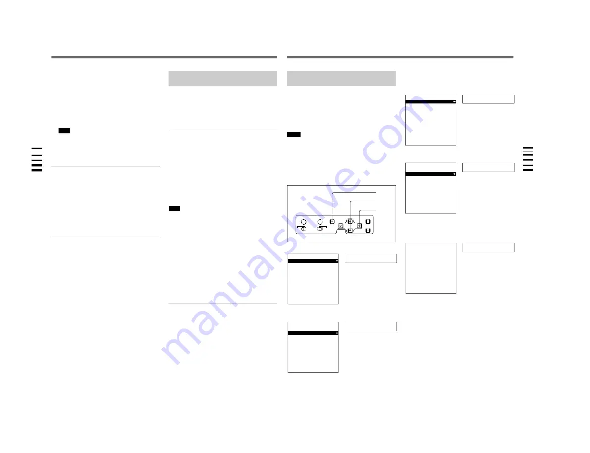
1
Press the MENU button on the menu control panel.
Setup menu
SYSTEM MENU
SETUP MENU
AUTO FUNCTION
HOURS METER
2
Press the
≥
button to select “AUTO FUNCTION”.
Auto func
SYSTEM MENU
SETUP MENU
AUTO FUNCTION
HOURS METER
3
Press the
÷
button.
This displays the items in the level 1 of the auto
mode execution menu.
QSDI DUB
AUTO FUNCTION MENU
QSDI DUBBING
TC INSERT
4
Press the
≥
button to select “TC INSERT”.
TC insert
AUTO FUNCTION MENU
QSDI DUBBING
TC INSERT
5
Press the
÷
button.
The following message appears.
Set tape!
TC INSERT
INSERT THE TAPE IN
THIS VTR.
ABORT:MENU KEY
7,8
3,5
2,4
1
SYNC PHASE
SC PHASE
MENU
MONITOR SELECT
RESET(NO)
SET(YES)
CH-
1/2
CH-
3/4
CH-
1/3
CH-
2/4
MIX
Time counter display
Monitor screen
(Continued)
Time counter display
Monitor screen
Time counter display
Monitor screen
Time counter display
Monitor screen
Time counter display
Monitor screen
Summary of Contents for DVCAM DSR-60
Page 2: ......
Page 54: ......
Page 174: ......
Page 220: ......
Page 236: ......
Page 238: ...8 2 N DSR 80 80P 60 60P SY 241B 241 CV101 CHARA SIZE 10 1 N DSR 60 80 ...
Page 242: ...8 2 P DSR 80 80P 60 60P SY 241B 241 CV101 CHARA SIZE 10 1 P DSR 60P 80P ...
Page 284: ......


