background image

E_MH_Installation_instructions_Skylux_Climax

20/11/2020

58/88

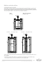
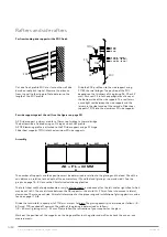
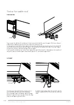
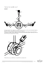
Finish

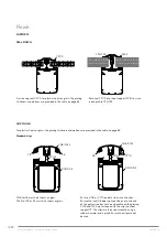
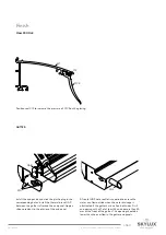
SUPPORTS

SEAL FINISH

CLIP FINISH

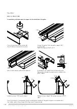
For plastic sheets or glass: the glazing thickness and options are provided in the table on page 83.

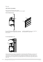
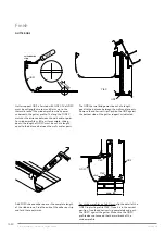
Standard clips

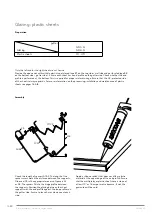
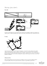
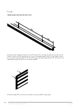
Push seal C8 or CY10 on both sides into the clips. 

Ensure that seal C8 does not continue up to the end 

of the gutter side but to the end profile on the glazing. 

CL16 and CL32 are fastened with the clips to sheet 

support TP. The clips are fastened manually using a 

rubber hammer and a plank. Ensure the clips are not 

dented.

CL16 for 16 mm thick sheets or glass.

CL32 for 25 or 32 mm thick sheets or glass.

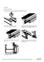
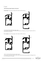
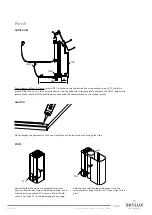
C2CX

C2CX

Y25/Y32

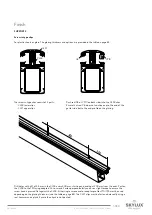
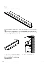
Push seal C2CX into sheet support TP(G) or into 

raised profile Y25/Y32. 

Finish using seal C2CX for plastic sheets or glass: The glazing 

thickness and options are provided in the table on page 83.

CL16/CL32

TP(G)

D1/D2/D3

C8

C8

C8

CY10

CL16/CL32

D1/D2/D3

TP(G)

Summary of Contents for Climax 36178

Page 1: ...CANOPY Climax Installation instructions Self supporting aluminium profile system EN Art N 36178...

Page 2: ...a roof always walk forwards Make sure there s enough light in the working zone Low hanging obstacles and falling loads Forbidden to walk under or within a radius of 1 m of a hanging or lifted load De...

Page 3: ...body as possible Parts of more than 25 kg must be lifted with at least 2 persons Personal protective equipment Work clothes safety shoes and helmet are mandatory for everyone Lifeline and harness are...

Page 4: ...ERVATORY ROOF WITHOUT THERMAL BRIDGE p 19 PLAN OF CONSERVATORY ROOF WITH THERMAL BRIDGE p 20 SPECIFIC INSTALLATION TIPS FOR THE CLIMAX SYSTEM WITHOUT THERMAL BRIDGE p 21 41 POSTS p 22 23 GUTTER p 24 2...

Page 5: ...E ROOF p 71 PREPARATION OF THE TIE BAR FOR THE SADDLE ROOF p 72 INSTALLATION OF THE TIE BAR FOR THE SADDLE ROOF p 73 SIDE FINISH OF THE SADDLE ROOF p 74 ANNEX p 75 84 LOAD GRAPHS p 76 80 LOAD GRAPHS F...

Page 6: ...CORNER PIECE 120 OUTSIDE CORNER PIECE 150 INSIDE CORNER PIECE 90 GD 1 GUTTER SUPPORT GD 2 GUTTER SUPPORT GD2C COVER FOR GUTTER SUPPORT GD2 GDP THERMAL BREAK GD2 SB HINGE BOTTOM WALL GUTTER G120A GUTTE...

Page 7: ...IN CLIP FOR 8 TO 34 MM CLSL TOP SCREW IN SIDE CLIP P POST PART 110 50 PC POST CLIP FOR P POSTS PCB POST CLIP BASE FOR P 98 POST 50 100 97A POST CLIP BASE FOR POST CLIP WITHOUT COAT 97B POST CLIP 100 P...

Page 8: ...MM FOR 32 MM SHEET Y16A RAISED PROFILE ALUMINIUM 16 MM Y16P THERMAL BREAK ABS 16 MM ACCESSORIES U16P REINFORCED PVC END PROFILE 16 MM WHITE U25P REINFORCED PVC END PROFILE 25 MM WHITE U32P REINFORCED...

Page 9: ...UPPORT COVER GAS1 GUTTER SLIDE END FOR G GD GAS2 GUTTER SLIDE END FOR GD GAS3 GUTTER SLIDE END FOR GD2 G G120AS GUTTER SLIDE END FOR G12OA GAP1 THERMAL END PANEL FOR GD1 GAP2 THERMAL END PANEL FOR GD2...

Page 10: ...T 98 AND BASE PLATE PV GC OUTLET SWIVEL 80 mm BUGS WUGS UNIVERSAL GUTTER SPOUT OUTLET GUTTER SPOUT 8423 CENTRAL DRAWING RING 8420 CENTRAL ROSETTE COVER 8425 RIDGE FIXATION 8424 END PIECE FOR THREADED...

Page 11: ...astic sheets can be damaged by these products Plastic sheets can result in settlement noise due to temperature fluctuations This will not affect the guarantee and will not be accepted as a claim Terms...

Page 12: ...ts ZD An additional 12 mm per side support must be added for applications with a side support cover ZDC The total conservatory width with 2 ZDCs is therefore 24 mm wider If the Climax is installed bet...

Page 13: ...with post P 100 mm in combination with post 98 or post 100 The 3 4 5 rule Determine the auxiliary point C1 based on O1 at a distance of 4 metres Use a 3 metre string and a piece of chalk to draw a cir...

Page 14: ...ermal bridge Determine the width B Fig 2 page 13 Width B of the Climax is the distance between the wall and the exterior of the side support An additional 12 mm must be added for applications with a s...

Page 15: ...th post P 100 mm in combination with post 98 or post 100 The 3 4 5 rule Determine the auxiliary point C1 based on O1 at a distance of 4 metres Use a 3 metre string and a piece of chalk to draw a circl...

Page 16: ...sills etc Make a slot in the walls against which the conservatory roof is to be installed Install a lead slab or zinc flashing We refer to page 10 Measuring your Climax pitched roof Height first join...

Page 17: ...0 mm sheet must have a clearance lengthwise of 1 5 cm u Never block the sheet lengthwise or widthwise Always ensure sufficient clearance u Never stick the sheet using silicone even when it does not da...

Page 18: ...ulating struc ture in the sheet are sensitive to foot knee and other impressions at the surface Please take enough precau tions during transport and installa tion Impressions in the sheet are not cove...

Page 19: ...11 A20 A21 A22 A23 A40 A41 A42 A30 A31 A32 A33 Overview of the drawing of the conservatory roof without thermal bridge A10 A11 Posts page 22 23 44 A20 A23 Gutters page 24 28 41 A30 A33 Wall profiles p...

Page 20: ...B11 B20 B21 B22 B23 B40 B41 B42 B30 B31 B32 B33 Overview of the drawing of the conservatory roof with thermal bridge B10 B11 Posts page 43 44 67 B20 B23 Gutters page 45 48 65 67 B30 B33 Wall profiles...

Page 21: ...20 11 2020 21 88 E_MH_Installation_instructions_Skylux_Climax Installation tips for the Climax system without thermal bridge...

Page 22: ...le for posts in combination with gutter support GD2 see page 81 The following posts can be used for roofs without a thermal bridge Standard posts accessories for the corner post accessories for the in...

Page 23: ...on a solid basis Position the posts over the brackets Position these perpendicularly level and shore these temporarily to ensure they do not fall over The top part of all posts must be completely alig...

Page 24: ...80 or calculate using the Climafast calculation application Gutter combination with reinforcement profile GD1 G Y10 V642 GD2 G Y10 PL165 PL105 The reinforcement profiles PL105 100 x 5mm are not suppl...

Page 25: ...using the Y10 Slide in the hinge profile S1 or S2 Cut out the opening for the water outlet Use a 80 mm circular drill for this task Slide in reinforcement profile V642 optional Installation of U brac...

Page 26: ...on product Connect the gutter G to the gutter support GD2 using the Y10 Slide in thermal bridge Y16P in the lowest detail of gutter support GD2 The length of Y16P matches the distance between the post...

Page 27: ...nd or connector profile GI Use silicone glue SG20 as sealant A raised profile GR can be installed on the gutter G Position the side gutter slide ends first and subsequently fasten the GR profile on to...

Page 28: ...eplaced by non self supporting hinge profile SB for this This profile is installed on a continuous upstand using adjusted fixing accessories to be provided by the customer Seal C11CX must be installed...

Page 29: ...ges must not be slid in continuously over the full length A 250 mm length every 250 mm is sufficient The Y16P is used to regulate the height The number of thermal bridges Y16P that are slid on to each...

Page 30: ...span or an expected heavy snow load Check the support length in relation to the glazing snow and wind load see the graphs of page 77 80 or use the Climafast calculation application Support Support wit...

Page 31: ...th at a right angle Cut the reinforced profiles to the right length and slide them into the aluminium support profiles For regular installation using plastic sheets the length of the reinforced profil...

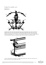
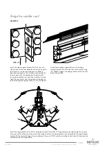
Page 32: ...equal parts of max 700 mm when using glass The glazing quantity is determined as follows B 60 mm 700 rounded off upwards The width of the glazing is determined as follows B 60 mm glazing units 22 mm...

Page 33: ...is not in the way laterally with regard to the finishing profile Allow for a clearance of at least 5 mm the side support will be fixed against a wall Install spacers A1 or A2 between the supports on...

Page 34: ...of the sheet is always upwards See pages 17 18 for more information on the processing installation and maintenance of plastic sheets Electrical facilities must be implemented for plastic sheets with...

Page 35: ...supports Slide seal C5 into the provided slot and press support seal C31 into the provided cut aways of spacer A1 or A2 The spacers fit into the hinge profile between the supports The glazing is there...

Page 36: ...the end profile on the glazing CL16 and CL32 are fastened with the clips to sheet support TP The clips are fastened manually using a rubber hammer and a plank Ensure the clips are not dented CL16 for...

Page 37: ...use a slight torque to ensure the screw head is pressed flat against the CLSB Either single screws and or adaptor profiles Y10 Y25 must be used depending on the glazing thickness see the table on pag...

Page 38: ...Position profile L16P against the exterior against the support profile Fasten profile L16P every metre sideways against the support with ZSG or against the wall using screws if the structure is to be...

Page 39: ...daptor profiles CY10 Y25 must be used depending on the glazing thickness see the table on page 84 Cut the CLL CLSL profile obliquely on the wall side in accordance with the roof pitch a Measure the di...

Page 40: ...r This opening should be lower than the overflow in the gutter end panels Install the end panels and click the plastic plug in the corresponding holes Apply a silicone sealant to the interior of the e...

Page 41: ...rt GD2 is finished with GD2C Cut the profile longitudinally at the indicated position The length of GD2C matches the distance between the walls and or posts Add silicone adhesive over the complete len...

Page 42: ...E_MH_Installation_instructions_Skylux_Climax 20 11 2020 42 88 Installation tips for the Climax system with thermal bridge...

Page 43: ...sts in combination with gutter support GD2 see page 84 The following posts can be used for roofs with a thermal bridge Standard posts accessories for the corner post accessories for the middle post Ba...

Page 44: ...for the middle posts can be installed without a base plate directly on a solid basis Position the posts over the brackets Position them perpendicular level and shore them temporarily to ensure they d...

Page 45: ...ation Gutters with reinforcement profile GD1 V642 G Y16P C11CX GD2 PL165 PL105 G Y16P C11CX Shorten the gutter by 10 mm if the gutter is to be mounted between two walls The 5 mm clearance on each side...

Page 46: ...onnect the gutter G to the gutter support GD1 using the Y16P Slide in the hinge profile S1 or S2 Cut out the opening for the water outlet Use a 80 mm circular drill for this task Slide in reinforcemen...

Page 47: ...55 PU 3x ZSB 4 10 6 6 55 Cut out the opening for the water drainage Use a 80 mm circular drill for this task Connect the gutter G to the gutter support GD2 using the Y16P Install an additional Y16P i...

Page 48: ...and or GI connector profile Use silicone glue SG20 as sealant Install the outlet in the gutter opening and seal using silicone The gutter slide ends have to be pre installed using self drilling ZGS s...

Page 49: ...be replaced by non self supporting hinge profile SB for this This profile is installed on a continuous upstand using adjusted fixing accessories to be provided by the customer Seal C11CX must be insta...

Page 50: ...50 mm length every 250 mm is sufficient The Y16P is used to regulate the height The number of thermal bridges Y16P which are slid on to each other between the bottom wall profile MB and the top wall p...

Page 51: ...elation to the glazing and the snow and wind load See the graphs on page 77 80 or use the Climafast calculation application Support Support with reinforcement D1 TP G D1 V642 TP G D2 TP G D2 V1044 TP...

Page 52: ...Freestanding side support ZD C5 TP G Y16P ZDC Side support against the wall ZD TP G L432 ZD TP G ZD2B TP G C5 Y16P ZD ZDC Y16P 5 mm TP G ZD L432 5 mm TP G ZD ZD2B L432 for the finish of the side suppo...

Page 53: ...side supports D1 D2 or ZD to the proper length at a right angle A steel reinforcement profile must be slid into the supports for a large span or expected heavy snow load Check the length of the suppor...

Page 54: ...ch side All useful information for the processing and installation of glazing plastics can be found on page 17 18 Divide the total width in equal part of 700 mm at most for glass The glazing quantity...

Page 55: ...t least 5 mm is required Install spacers A1 or A2 between the supports on hinge profile S1 or S2 Support seal C5 plastic sheets or support seals C5 C31 glass must be installed in here For more informa...

Page 56: ...ards For more information on the processing installation and maintenance of plastic sheets see pages 16 18 Assembly Check the length of spacers A1 A2 The length of the spacers must match the distance...

Page 57: ...Slide seal C5 into the groove and push support seal C31 into the cut aways of spacers A1 or A2 The spacers fit into the hinge profile between the supports The glazing is therefore supported on four si...

Page 58: ...the end profile on the glazing CL16 and CL32 are fastened with the clips to sheet support TP The clips are fastened manually using a rubber hammer and a plank Ensure the clips are not dented CL16 for...

Page 59: ...use a slight torque to ensure the screw head is pressed flat against the CLSB Either single screws and or adaptor profiles Y10 Y25 must be used depending on the glazing thickness see the table on page...

Page 60: ...ion the L16P profile between the support and the wall to ensure that the support lip is at the same height as the top side of the glazing Fasten the top lip of the L16P profile every 100 cm against th...

Page 61: ...t seal C8 does not continue up to the end of the gutter side but to the end profile on the glazing CL16 and CL32 are fastened with the clips to sheet support TP The clips are fastened manually using a...

Page 62: ...the ends Fasten the CLSB to the TPG using adapted Hi Lo screws Fasten perpendicularly and use a slight torque to ensure the screw head is pressed flat against the CLSB Either single screws and or adap...

Page 63: ...or CY10 into the CLL Ensure that seal C8 does not continue up to the end of the gutter side but to the end profile on the glazing Screw in clips for plastic sheets of glass with a thickness of 16 25...

Page 64: ...Either single screws and or adaptor profiles Y10 Y25 must be used depending on the glazing thickness see the table on page 83 The clips are fastened manually using a rubber hammer and a plank Ensure...

Page 65: ...break GAP between the gutter rafter and the end panel Apply a silicone sealant to the interior of the end panel A frontal UGS water outlet is required to ensure the water can flow outside when the wa...

Page 66: ...tween the walls and or posts The GDP thermal bridge must be cut at a length equal to the distance between the walls and or posts Remove the adhesive strips Position the GDP against the bottom side of...

Page 67: ...the GD2C profile does not exceed the thermal break of the window profile GLAZING Do not forget to apply sealant to the end profiles on the plastic sheets on the gutter side POSTS Check whether the pos...

Page 68: ...E_MH_Installation_instructions_Skylux_Climax 20 11 2020 68 88 Specific instruction tips for the saddle roof Climax system...

Page 69: ...d using two sets of wall profiles MB MT Y16P that are assembled back to back using adaptor profiles Y10 The number of thermal bridges Y16P between the bottom wall profile MB and the top wall profile M...

Page 70: ...les must be slanted Use the connection pins 909 to connect the profiles When the top wall profile MT is discontinuous the connection at the bottom must be sealed using self adhesive aluminium tape not...

Page 71: ...he hinge profile HM 17 Install the ridge support bracket NCZ to the wall Check whether the foundation and the walls on which the structure is to be anchored have a sufficient load bearing capacity The...

Page 72: ...the side support profile D1 or D2 with a bolt M10 Repeat every 2 supports See the specific installation tips for the Climax single pitch roof in this manual for information on the assembly of the gut...

Page 73: ...l connection between the supports When you are certain about the position you can cut the coated tube to size and slide it over the threaded bars Only remove the support from the ridge profile when th...

Page 74: ...h screw in type CLSB with CLST clips At the top of the ridge this side finish will be covered by the ridge end panel NASZ Use 4 coated screws ZSG for this SADDLE ROOF WITH THERMAL BRIDGE The side fini...

Page 75: ...20 11 2020 75 88 E_MH_Installation_instructions_Skylux_Climax Annex load graphs and special applications installation tips for the Climax system...

Page 76: ...files when installed on top of each other A possible bending of the gutter profile above the sliding doors should therefore be taken into account When the selected gutter support cannot be installed w...

Page 77: ...ou select gutter support GD1 that will make allowances for a free span of 2700 mm You then install an extra post in the middle for support The span is the distance P between the posts In this example...

Page 78: ...length of the support between the hinge profiles in relation to the load and the depth D of the roof The maximum bending is 1 200 In other words a bending of 1 cm for a free span of 200 cm The load i...

Page 79: ...ither you select gutter support GD2 with reinforcement PL165 that will make allowances for a free span P of up to 5080 mm Or you select gutter support GD1 with reinforcement V642 that will make allowa...

Page 80: ...hinge profiles in relation to the load and the depth D of the roof The maximum bending is 1 300 In other words a bending of 1 cm for a free span of 300 cm The load is the sum of the weight of the glaz...

Page 81: ...tom With thermal bridge The outer post section P or the post clip PC is 70 mm longer than the inner post section P in relation to assembled support posts HN HG The thermal bridges and post clip base P...

Page 82: ...ss For glazing 8 21 mm GVT GVT single glazing For double glazing or plastic sheets 21 mm GVB GVT Y16P Y10 Measurement and preparation GVT GVT GSP8 GSP8 L1 L2 SG20 SG20 SG20 SG20 27 mm Ltot Glazing len...

Page 83: ...in relation to the glazing thickness according to the table on page 80 The GVT profile is also used as the bottom profile without spacers for single glazing 8 10 and 12 mm or glazing up to 21 mm Posit...

Page 84: ...S32 3 19 mm HL42 S32 3 20 mm HL42 Y25 S32 3 21 mm HL42 Y25 S32 3 22 mm HL42 Y25 Y25 S32 3 23 mm HL42 Y25 Y25 S32 3 24 mm HL42 Y25 Y25 S32 3 25 mm HL42 Y25 S32 3 26 mm HL42 Y25 Y25 S32 3 27 mm HL42 Y2...

Page 85: ...20 11 2020 85 88 E_MH_Installation_instructions_Skylux_Climax...

Page 86: ...E_MH_Installation_instructions_Skylux_Climax 20 11 2020 86 88...

Page 87: ...20 11 2020 87 88 E_MH_Installation_instructions_Skylux_Climax...

Page 88: ...0 56 20 00 00 F 32 0 56 21 95 99 INFO SKYLUX BE WWW SKYLUX BE ONLY USE ORIGINAL PARTS DELIVERED BY SKYLUX EVERY GUARANTEE IS CANCELLED IF NON ORIGINAL PARTS ARE USED THESE GUIDELINES ONLY HAVE AN ADV...

Reviews: