09/08
Operating Instructions ACU
191
If the mains voltage is restored before a switch-off is affected by the mains undervol-
tage detection system, the drive is accelerated to its reference frequency at the set
acceleration or according to the parameter
Acceleration on mains resumption
674. If
the value of parameter
Acceleration on mains resumption
674
is set to the default
value of 0.00 Hz/s, the drive is accelerated at the values set for the ramp parameters
Acceleration (clockwise)
420 or
Acceleration (anticlockwise)
422
.
Parameter
Settings
No.
Description
Min.
Max.
Fact. sett.
671
Mains failure threshold -200.0
V -50.0 V
-100.0 V
672 Reference mains support value
-200.0 V
-10.0 V
-40.0 V
Note:
The frequency inverter reacts to the signals at the control inputs both when
the power failure regulation is switched on and in normal operation. A con-
trol via externally supplied control signals is only possible in the case of a
no-break supply. As an alternative, supply for the control signals through the
frequency inverter is to be used.
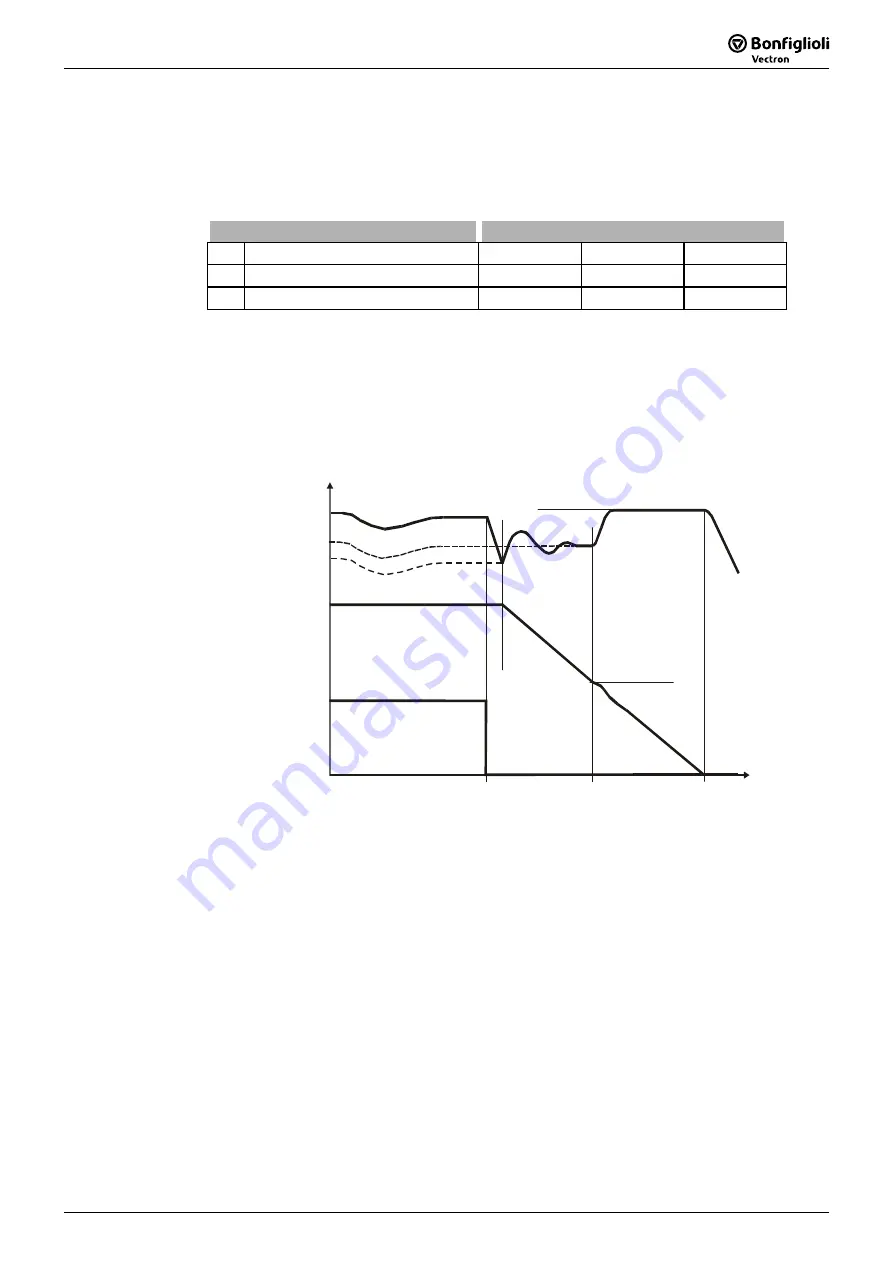
Operation mode power failure regulation
f
671
676
672
Mains voltage
Power failure
Off
t
Ud
Ud, f
675
673 or 683
The DC link voltage which is available in the case of a power failure is supplied by the
motor. The output frequency is continuously reduced and the motor with its rotating
masses is switched over to generator operation. The maximum reduction of the out-
put frequency is done at the current set by the parameter
Gen. ref. current limit
683
or the ramp
Mains support deceleration
673 until the frequency limit
Shutdown thre-
shold
675
is reached. If the energy of the system for bridging the mains failure is not
sufficient, the delay is affected at maximum ramp gradient as from the
Shutdown
threshold
675
.
The time required until the motor has come to a standstill results from the regenera-
tive energy of the system which results in an increase in the DC link voltage. The DC
link voltage set with the parameter
Reference shutdown value
676 is used by the
voltage controller as a control figure and kept constant. The voltage rise enables
optimization of the braking behavior and the time until the drive has come to a
standstill. The behavior of the controller can be compared to stopping behavior 2
(Sh Stop), as the voltage controller brings the drive to a standstill at the
maximum deceleration ramp and supplies it with the remaining DC link voltage.
Operating Instructions ACU
191
09/08
Summary of Contents for Bonfiglioli Vectron ACTIVE CUBE ACU 201 Series
Page 1: ...ACTIVE CUBE Operating Instructions Frequency Inverter 230V 400V 0 25 kW 132 kW ...
Page 2: ......
Page 259: ......


