background image

3 - 6

3 Maintenance

Maintenance Procedures – All Models

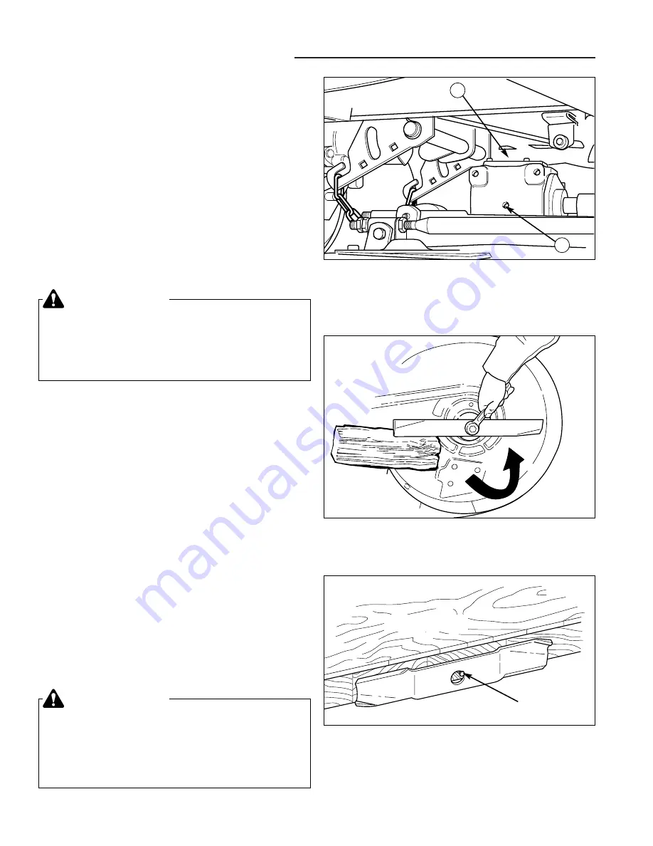
Check Mower Deck Gear Box Oil

To check the mower deck gear box oil:

1. Remove the plugs from the top and side of the gear

box (Figure 4).

2. Add SAE 85W-90 oil through the top hole until oil

comes out the side fill hole. Place a shop towel under
the side opening to keep oil off the belt and pulleys.

3. Replace the plugs and wipe up any spilled oil.

Figure 4.  Gear Box Fill Plug Location
A. Top Fill Plug

B. Side Fill Plug

A

B

SERVICING THE MOWER BLADES

1. Remove mower from the tractor. See Mower

Installation & Removal.

2. Blades should be sharp and free of nicks and dents.

If not, sharpen blades as described in the following
steps.

3. To remove blade for sharpening, use a wood block to

hold blade while removing the blade mounting cap-
screw (Figure 5).

4. Use a file to sharpen blade to fine edge. Remove all

nicks and dents in blade edge. If blade is severely
damaged, it should be replaced.

5. Balance the blade as shown in Figure 6. Center the

blade’s hole on a nail lubricated with a drop of oil. A
balanced blade will remain level.

6. Reinstall each blade with the tabs pointing up toward

deck as shown in Figure 7. Secure with a capscrew
(D), spring washer (C), and spline washer (B). Be
certain the spline washer is aligned with the shaft
splines. Use a wood block to prevent blade rotation,
and torque capscrews to 45-55 ft. lbs. (61-75 N.m.).

WARNING

For your personal safety, do not handle the sharp
mower blades with bare hands. Careless or
improper handling of blades may result in serious
injury.

WARNING

For your personal safety, blade mounting
capscrews must each be installed with a hex
washer and spring washer, then securely tightened.
Torque blade mounting capscrew to 45-55 ft. lbs.
(61-75 N.m.).

LOOSEN

Figure 5.  Removing the Blade

Figure 6.  Balancing the Blade

Workbench

Nail

Not 

for 

Reproduction

Summary of Contents for AGCO Allis 2000 Series

Page 1: ...USE N o t f o r R e p r o d u c t i o n...

Page 2: ...7 1 7 46 8 Power Steering Service 8 1 8 12 9 Drive Control Service 9 1 9 12 10 U Type Hydrostatic Unit Service 10 1 10 14 11 Transaxle Removal Installation 11 1 11 10 12 Brake System Service 12 1 12...

Page 3: ...per Tool Use 1 7 Personal Protective Equipment 1 7 Fuel Handling 1 7 Exhaust 1 8 Battery 1 8 Elevation of Unit 1 8 Electrical System 1 8 Work Area 1 9 Compressed Air 1 9 Lubricants 1 9 General Servici...

Page 4: ...tions These three basic types are referred to throughout this manual When a service procedure is specific to a certain model that model will be identified as one of the groups listed at right Model Co...

Page 5: ...xport 1693561 Legacy 25HP w Hydraulics 1693562 2025 25HP w Hydraulics 1693563 2925 25HP w Hydraulics 1693738 24 5HP Tractor Generic TRACTORS Description Description MOWER DECKS 1692860 60 Mower Deck 1...

Page 6: ...eloped to permit mechanics and service technicians to perform most service procedures quickly and effectively it is assumed that those using this manual will have some outdoor power equipment service...

Page 7: ...or in place Slow down before turning Never leave a running unit unattended Always disen gage the PTO set parking brake stop engine and remove keys before dismounting Turn off the PTO switch to disenga...

Page 8: ...ur safety as well as those who operate the equipment and it is important If any of these decals are lost or damaged replace them at once See your Parts Manual for replacement informa tion These labels...

Page 9: ...mall tools and tool attachments left on the equipment can fall into the cutting path when the unit is placed into service and become a hazard to bystanders if struck by the mower blades PERSONAL PROTE...

Page 10: ...rom the battery Keep battery securely fastened in position with vent tube directed down and out of battery compartment Replace battery if electrolyte leakage occurs Make sure the battery vent tube is...

Page 11: ...n done using and store or dispose of properly 1 9 1 General Information Safety Rules GENERAL SERVICING Always check safety devices and switches for proper operation never alter these devices or make t...

Page 12: ...CTION Once cleaned bearings can be properly inspected for wear scratches visible damage such as corrosion cracked seals or scorching and rough or noisy opera tion Bushings can be visually checked for...

Page 13: ...Factory supplied paints are available that provide both an accurate color match and superior corrosion resistance Required Tools and Equipment All repairs in this manual can be accomplished with stan...

Page 14: ...ast iron sleeve aluminum crankcase Electrical 15 Amp alternator 12 volt 500 cranking Amps 85 minute reserve capacity Governor Mechanical no load setting 3600 rpm idle speed 1800 rpm Oil Capacity 2 1 q...

Page 15: ...andard Tachometer Standard Hourmeter Standard Indicator Lights Engine Oil Pressure Standard Battery Voltage Standard PTO Light Front Rear Standard Glow Plug Standard Water Separator Standard FUEL SYST...

Page 16: ...ORS EAR Tractor Only at Full Throttle 83 9 Tractor with 48 Mower Tractor with 60 Mower 86 2 Meets applicable safety standard ANSI B71 1 1996 SEAT Style Height 18 high back Suspension Tapered spring Ad...

Page 17: ...tapping screws thread forming screws sheet metal screws and socket head setscrews 2 Recommended seating torque values for locknuts a For prevailing torque locknuts use 65 of Grade 5 torque b For flan...

Page 18: ...1 16 1 General Information Notes N o t f o r R e p r o d u c t i o n...

Page 19: ...1 2 Troubleshooting Table of Contents SECTION CONTENTS Troubleshooting Troubleshooting Chart 2 2 Troubleshooting Common Mowing Problems 2 4 SECTION 2 TROUBLESHOOTING N o t f o r R e p r o d u c t i o...

Page 20: ...e Manual 10 Safety interlock switch Replace as needed 7 11 Spark plug s faulty fouled Clean and gap or replace See Engine Manual or incorrectly gapped gas only 12 Water in fuel Drain fuel and refill w...

Page 21: ...lated Check and inflate tires 3 equally or properly Mower cut is 1 Engine speed too slow Always mow at full throttle N A rough looking 2 Ground speed too fast Slow down N A 3 Blades are dull Sharpen o...

Page 22: ...installed incorrectly Reinstall the blades correctly 6 18 Stepped Cutting Streaking Streaking Streaking occurs when thin strips of uncut grass are left behind the mower Streaking is usually caused by...

Page 23: ...ll or worn Sharpen or replace the blades 3 6 18 Blades are damaged Replace the blades 6 18 Deck is clogged with grass clippings Clean out the deck N A Deck shell is damaged Repair or replace the deck...

Page 24: ...2 Troubleshooting Notes 2 6 N o t f o r R e p r o d u c t i o n...

Page 25: ...Test 3 7 Lubrication 3 8 Checking the Battery Fluid 3 10 Cleaning the Battery and Cables 3 10 Maintenance Gas Engine Models Oil and Filter Change 3 11 Check Change Air Filter 3 11 Inspect Spark Plug W...

Page 26: ...the proper level with water and is fully charged Battery life will be increased if it is removed put in a cool dry place and fully charged about once a month If battery is left in unit disconnect the...

Page 27: ...hours of operation More often in hot over 85 F 30 C weather or dusty operating conditions Before Before Every Every Every Spring SAFETY ITEMS First Use Each Use 5 Hours 25 Hours 100 Hours Fall Check...

Page 28: ...l Change Engine Oil Filter Lubricate Tractor Mower Check Tire Pressure Check Transmission Fluid Change Transmission Fluid Filter Every 400 Hours Drain Replace Fuel Filter Clean Battery Cables Clean Sh...

Page 29: ...e is no oil in the tube add Type F automatic transmission oil a few ounces at a time The transmission fill tube is located under the seat Figure 3 Changing Transmission Fluid and Filter The transmissi...

Page 30: ...de to fine edge Remove all nicks and dents in blade edge If blade is severely damaged it should be replaced 5 Balance the blade as shown in Figure 6 Center the blade s hole on a nail lubricated with a...

Page 31: ...d OR Operator rises off seat with brake pedal NOT fully depressed or parking brake disengaged Test 4 Blade Brake Check Mower blades and mower drive belt should come to a complete stop within five seco...

Page 32: ...is recommended automotive type lithium grease may be used when this is not available OIL hydro linkage brake linkage deck height adjustment linkage Generally all moving metal parts should be oiled whe...

Page 33: ...er Arbor Lubrication Figure 13 Mower Drive Shaft Figure 11 Deck Lubrication Grease the Electric Lift Rod Grease Fitting Yearly Grease the Deck Belt Idler Pulley Arm Grease Fitting Yearly 48 Mower 60 M...

Page 34: ...water 4 Clean the battery terminals and cable ends with a wire brush and battery terminal cleaner until shiny 5 Reinstall the battery in the battery compartment and secure with the battery hold down...

Page 35: ...D Oil Fill B Oil Drain Tube E Dipstick C Oil Drain Valve Figure 18 Kawasaki Engine A Spark Plug C Coolant Reservoir B Oil Filter D Air Filter C B D F E E D A C C B D Check Change Air Filter Refer to...

Page 36: ...fuel line with hose clamps 7 Reconnect the negative battery cable when finished WARNING Gasoline is highly flammable and must be handled with care Never fill the tank when the engine is still hot from...

Page 37: ...ARNING Diesel fuel is highly flammable and must be handled with care Never fill the tank when the engine is still hot from recent operation Do not allow open flame smoking or matches in the area Avoid...

Page 38: ...out the front and back of the radiator 4 Reinstall the screen Figure 23 Change Oil Filter A Oil FIlter D Latch B Dipstick E Screen C Air Filter E C D A B 3 Maintenance Maintenance Diesel Engine Models...

Page 39: ...ion Adjustment 4 3 Differential Lock Cable Adjustment 4 3 Neutral Adjustment 4 4 PTO PTO Clutch Adjustment 4 5 Mower Deck Leveling 4 6 Pulley Stop Adjustment 48 Mower Only 4 7 Gauge Wheel Adjustment 5...

Page 40: ...ro cedure should be followed The normal angle of the tab is about 45 degrees and setting the tab to that point would be a good starting point 1 Park the tractor on a level surface 2 Place blocks in fr...

Page 41: ...stment nuts A Figure 4 on the for ward cable shroud located under the left foot rest 2 Loosen the adjustment nuts so that the cable is slack and the foot pedal rod B drops down 3 Tighten the cable unt...

Page 42: ...er A and neutral pin E If not loosen the carriage bolt securing the neu tral gate spacer A 6 Slide the spacer up and down until the neutral spring B is contacting both sides of the neutral pin E and n...

Page 43: ...on when the gauge is inserted and removed and make any necessary adjustments by tightening or loosening the adjustment nuts NOTE Adjustment at one location will change adjust ment at the two other slo...

Page 44: ...t to Back Leveling 7 See Figure 8 Loosen the outside nut A then turn the eccentric nut B to raise or lower the left side of the deck Repeat on the right side of the deck When the mower deck is level h...

Page 45: ...of cut When using higher cutting heights set the wheels in the lower position When using lower cutting heights set the wheels in the upper position To adjust 1 Remove the hairpin clip A B Figure 11 2...

Page 46: ...height range or if scalping occurs at lower cutting heights due to uneven terrain Idler Pulley Adjustment 60 Mower Only If the mower deck belt has stretched over time the outermost idler pulley A Fig...

Page 47: ...ctor Belt Replacement PTO Belt Replacement 5 2 Mower Deck Belt Replacement 48 Mower Deck Drive Belt Replacement 5 3 54 Mower Deck Drive Belt Replacement 5 4 60 Mower Deck Drive Belt Replacement 5 5 SE...

Page 48: ...he lower PTO pulley E idler pulley C PTO clutch pulley B and the fan F 5 Replace the new belts D one at a time on the lower pulley E idler pulley C PTO clutch pulley D and the fan F Figure 2 Figure 1...

Page 49: ...and check for free movement see LUBRICATION 7 Install the new drive belt as shown in the diagram in Figure 4 8 Check that the pulley stop B Figure 5 is properly aligned See PULLEY STOP ADJUSTMENT 9 C...

Page 50: ...bearing damage 6 Lubricate the idler arm pivot with multi purpose lithium grease and check for free movement 7 Install the new drive belt as shown in the diagram in Figure 7 8 Complete installation by...

Page 51: ...ge 6 Lubricate the idler arm pivot with multi purpose lithium grease and check for free movement 7 Install the new drive belt as shown in the diagram in Figure 9 8 Complete installation by following s...

Page 52: ...5 Belt Replacement Notes 5 6 N o t f o r R e p r o d u c t i o n...

Page 53: ...and Installation 6 4 Elevating the Tractor Elevating Rear End for Safe Service 6 5 Elevating Front End for Safe Service 6 6 Wheel Service Rear Wheel Removal and Installation 6 7 Front Wheel Removal a...

Page 54: ...ion switch to RUN position and set the mower cutting height to minimum it is not necessary to start the engine 14 Turn the ignition switch to the OFF position 15 Disconnect the electrical connection f...

Page 55: ...sing the two short pins C Figure 9 and safety clips 12 Attach the hitch bucket A Figure 5 to the mower deck using the one long pin B and safety clip 13 Start the engine 14 Fully raise the attachment l...

Page 56: ...ned with the hex shaft Use a wooden block A to prevent blade rotation and torque the capscrew to 45 55 ft lbs 61 75 Nm WARNING For your personal safety do not handle the sharp mower blades with bare h...

Page 57: ...moval NOTE Because the front axle can pivot always support both sides of unit evenly 4 Support the rear of the rider on jackstands Figure 10 positioned under the rear frame DANGER PREVENT SERIOUS INJU...

Page 58: ...g an overhead hoist Figure 11 or a floor jack carefully raise the front end up 1 to 2 NOTE For overall unit stability during service do not lift front end higher than required for tire removal NOTE Be...

Page 59: ...all Bearing D C E B A F FRONT WHEEL SERVICE Front Wheel Removal and Installation Refer to Figure 14 1 Elevate the front of the unit see Elevating Front End for Safe Service in this section 2 Remove th...

Page 60: ...such as a cracked case or cover 2 Check the tightness of the battery cable terminals and connections to ensure good electrical connec tions 3 Check the entire length of each cable for cracks and fray...

Page 61: ...and detach them from the starter sole noid and ground terminals Note the routing of each cable to ensure correct installation 3 If you are replacing either the positive negative or both cables replace...

Page 62: ...cable A and negative cable clamp B away from the negative battery post D Assemble in reverse order WARNING Be careful when handling the battery Avoid spilling electrolyte Keep flames and sparks away...

Page 63: ...HE BATTERY 1 Set the battery in the battery compartment 2 Secure the battery by using the battery clamp H Figure 19 and 20 rods G hex nuts E and wash ers F 3 Replace battery guard I Figure 19 diesel e...

Page 64: ...until the specific gravity of the electrolyte is 1 250 or higher and the electrolyte temperature is at least 60 F The best method of making certain a battery is fully charged but not over charged is...

Page 65: ...wired to starter or solenoid 5 Connect the other end of same cable to same post marked positive on booster battery 6 Connect the second cable negative to other post of booster battery 7 Make final co...

Page 66: ...expose battery to open flame or electric spark battery action generates hydrogen gas which is flammable and explosive Do not allow battery acid to contact skin eyes fabrics or painted surfaces Batteri...

Page 67: ...viceable In the event the alternator becomes defective exchange the alterna tor for a new or rebuilt part at your local engine manufac turer parts store or dealership parts department Charging System...

Page 68: ...talled 2 Before the tractor is started engaged the parking brake disengaged the front PTO switch PTO switch pushed in and sit in the operator s seat 3 Start the engine and set at full throttle 4 Engag...

Page 69: ...l Testing Information 7 34 A Check Clean Wires and Connectors 7 34 B Check Clean Ground Cable 7 34 C Battery Tests 7 35 D Isolated Battery Voltage Check 7 36 E Charging Voltage Check 7 36 F Preheat Ti...

Page 70: ...ng brake turn the ignition switch off remove the key disconnect the spark plug wire and disconnect the negative battery cable properly If several components malfunction at the same time chances are th...

Page 71: ...n switch through the safety switches to the solenoid 2 If all safety conditions are met the safety interlock switches allow current to pass through the solenoid activating the solenoid The activated s...

Page 72: ...d VOM is a volt ohm meter multi meter or equivalent VDC is volts of direct current or the VOM setting used to measure DC voltage Ohm is units of resistance or the VOM setting used to measure resistanc...

Page 73: ...TAIL LIGHT ASSEMBLY 6 2 BULB Tail Light 7 2 NUT Hex Flange 8 2 NUT KEPS Lock 9 2 CAPSCREW 10 1 SWITCH Cruise Fuel Gauge To Upper Harness To Rear PTO Optional 5 1 2 3 4 7 8 9 10 7 6 NOTE Unless noted...

Page 74: ...ne Ground To Voltage Regulator 30 11 1 2 3 4 5 6 8 9 10 12 13 14 15 5 5 16 17 18 19 20 21 22 23 24 25 26 27 29 32 33 34 5 7 28 31 NOTE Unless noted otherwise use the standard hardware torque specifica...

Page 75: ...ge 15 1 WASHER Internal Tooth 16 1 CABLE Battery to Starter 17 1 LOCKWASHER 18 1 NUT Hex Jam 19 1 COVER Starter Terminal 20 1 COVER Positive Battery Terminal 21 1 CABLE Battery to Ground 22 1 BATTERY...

Page 76: ...19 20 21 22 23 24 25 26 27 28 29 30 32 33 34 5 7 31 To Lower Harness To Engine Ground To Front PTO To Relay NOTE Unless noted otherwise use the standard hardware torque specification chart Figure 3 E...

Page 77: ...ge 15 1 WASHER Internal Tooth 16 1 CABLE Battery to Starter 17 1 LOCKWASHER 18 1 NUT Hex Jam 19 1 COVER Starter Terminal 20 1 COVER Positive Battery Terminal 21 1 CABLE Battery to Ground 22 1 BATTERY...

Page 78: ...low Plug Relay To Preheat Timer To Glow Plugs To Engine Temperature Sender To Fuel Filter To Rear PTO Switch Optional To Engine Mount Frame To PTO Clutch To Oil Pressure Sender To Fuel Solenoid To Sta...

Page 79: ...COVER Key Switch 14 1 NUT Hex Flange 15 1 WASHER Internal Tooth 16 1 COVER Terminal 17 1 FUSE 30 Amp Automotive Early Models Only 18 1 SWITCH Front PTO 19 1 BREAKER Circuit 20 2 CAPSCREW 21 1 SWITCH...

Page 80: ...BLACK RED YELLOW RED BLACK RED BLACK RED BLACK BLACK BLACK WHITE RED BLK BLACK YELLOW BLUE RED BLUE RED BLUE RED BLACK RED BLACK WHITE RED BLACK BLACK RED RED BLUE BLACK BLACK BLACK BLACK BLACK RED BL...

Page 81: ...BLACK YELLOW BLACK BLACK BLACK BLACK ORANGE BLUE W LT BLUE GREEN BLACK BROWN BLACK BLK BR0WN BLACK RED YELLOW HEIGHT OF CUT MOTOR 1715885 1 2 STARTER 1 2 3 4 5 ENGINE ALTERNATOR OIL SWITCH ENGINE PLUG...

Page 82: ...BLACK BLACK WHITE GROUND GROUND BLACK RED BLACK BLACK YELLOW VIOLET WHITE BLUE RED BLACK BLACK RED BATTERY BLACK RED RED BLACK BLUE YELLOW BLACK BLUE RED YELLOW BLACK BLACK FRONT CLUTCH RED BLACK RED...

Page 83: ...e purpose is to supply current to the glow plug for a timed duration before the engine is started This allows the glow plugs to heat up to a point that will ignite the compressed fuel Power is supplie...

Page 84: ...the clutch is connected to the PTO clutch indicator lamp on the instrument panel NOTE When there is not a rear PTO clutch installed jumpers will need to be installed on the connector for the rear PTO...

Page 85: ...ypical Ignition Shutdown Linear Circuit Diagram Air Cooled Models N O N C N C PEDAL SWITCH w PEDAL UP N O N O PTO SWITCH OFF POSITION SEAT SWITCH UNOCCUPIED KEY SWITCH ON POSITION BATTERY To Alternato...

Page 86: ...e 15 Headlight Switch Replacement A Dashboard C Headlight Switch B Wire Harness D Locking Tabs B 3 Unplug the wire harness B from the back of the igni tion key switch C 4 Remove the cap F using a scre...

Page 87: ...t switch is located in the dashboard on the right hand side of the steering wheel The height of cut switch sends power to the outlet under the left foot rest 1 Disconnect and secure the negative batte...

Page 88: ...l contains the RPM gauge temperature gauge and warning status lights Other than the light bulbs the instrument panel contains no replaceable parts and is serviced as an assembly If necessary refer to...

Page 89: ...isconnect the wire harness 4 Remove the screws C Figure 23 nuts E and washers D from the switch A and frame F 5 Remove the switch A 6 Install switch in reverse order of removal 4 Remove the screws C F...

Page 90: ...ard heat shield will need to be removed see Section 14 HOOD DASH FOOT REST SERVICE 2 Remove the light bulb socket A Figure 25 from the bezel 8 by twisting it counterclockwise and pulling it out 3 Use...

Page 91: ...o the fire wall A 4 Install in reverse order of removal A E C B F F Figure 29 Fuel Filter Diesel Models A Fuel Filter FUEL FILTER See Figure 29 All models have an in line fuel filter strainer only the...

Page 92: ...nt Sensor B Sensor Wire IGNITION COIL MAGNETO Refer to the engine manufacturer s manual for specific information regarding engine component testing and replacement OIL PRESSURE SENSOR All models conta...

Page 93: ...low charts provide an easy reference to the most common electrical problems which may occur It assumes that there is an actual defective component in the electrical system and that all mechanical and...

Page 94: ...O switch Refer to I PTO Switch Test Replace PTO switch Component Tests OK Component Fails Test Worn or malfunctioning brake pedal switch Refer to M Brake Pedal Switch Tests Replace the brake pedal swi...

Page 95: ...Pedal Switch Tests Replace the brake pedal switch Component Tests OK Component Fails Test Check the seat switch Refer to O Seat Switch Test Replace the seat switch Component Tests OK Component Fails...

Page 96: ...t timer Refer to F Preheat Timer Test Replace the preheat timer Component Tests OK Component Fails Test Engine will turn over but will not start Diesel Models Check glow plug relay Refer to G Glow Plu...

Page 97: ...witch Test Replace the seat switch Component Fails Test Check the PTO switch Refer to I PTO Switch Test Replace the PTO switch Component Tests OK Component Fails Test PTO clutch will not engage All Mo...

Page 98: ...Refer to H Ignition Switch Tests Replace the ignition switch Done Component Fails Test Battery not charging All Models Check charging voltage Refer to E Charging Voltage Check Replace the defective e...

Page 99: ...connectors or wiring Refer to A Check Clean Wires and Connectors Replace repair damaged wires or connectors Component Tests OK Component Fails Test Battery connections dirty loose or worn battery Ref...

Page 100: ...on All Models Worn or malfunctioning cruise control switch Refer to K Cruise Control Switch Test Replace the cruise control switch Component Tests OK Component Fails Test Done Worn or failed PTO switc...

Page 101: ...7 33 7 Electrical System Service Troubleshooting Notes N o t f o r R e p r o d u c t i o n...

Page 102: ...y cable ground cable from the engine 3 Clean the battery and cable terminals with a wire brush until the metal is shiny 4 Using a VOM set to Ohm test the continuity of the cable Figure 33 The VOM shou...

Page 103: ...ap when done C 3 TEST BATTERY VOLTAGE 1 Test the battery voltage set VOM to VDC 2 Place one test probe of the VOM on the batteries positive post and one probe on the negative post see Figure 35 Note a...

Page 104: ...ted Then reconnect the battery terminals with an amp meter in series with the battery and terminal There should be no current draw off the battery when all accessories are off and the ignition key swi...

Page 105: ...lamp and not an electronic testing lamp or LED light emitting diode type of test lamp 3 Connect one end of the jumper C to the positive Figure 38 Testing Preheat Timer A 12 Volt DC Lamp Tester C Test...

Page 106: ...these tests the ignition switch needs to be removed from the dashboard TEST START POSITION NOTE To perform this test the ignition key switch may need to be placed in a vice to hold the switch 1 Set V...

Page 107: ...ch Tests 5 Pin Steel Body Early Models 5 Repeat steps 2 through 4 for each combination of ter minals listed in the table for the OFF circuit of the appropriate figure Figure 40 for 5 pin steel body sw...

Page 108: ...control panel for testing Refer to the PTO Switch Replacement procedures located in this section 1 Pull the wire harness off the back of the switch 2 Place the PTO switch in the OFF position knob pul...

Page 109: ...rs between the accessory power connector and the switch and check the wiring Then check the height of cut switch Figure 46 Testing Accessary Connector K Cruise Control Switch Test The cruise control s...

Page 110: ...board See Section 8 POWER STEERING SYS TEM SERVICE 2 Remove the connector from the height of cut switch 3 Remove the height of cut switch from the control panel 4 Set VOM to Ohm 5 Press the switch to...

Page 111: ...N C normally closed seat switch When the seat is unoccupied the switch is closed and will conduct current Sitting in the seat opens the switch 1 Tilt the seat forward and pull the wire harness off th...

Page 112: ...utch Refer to Section 16 PTO CLUTCH SERVICE for com pete PTO clutch testing information and replacement procedures R Headlight Switch Test 1 If needed remove the steering wheel and dashboard See Secti...

Page 113: ...level should increase 6 If the voltage does not change or is at or near zero volts dc remove the signal wire D Figure 54 from the fuel level sensor which is the center wire and ter minal B 7 Connect...

Page 114: ...7 46 7 Electrical System Service Notes N o t f o r R e p r o d u c t i o n...

Page 115: ...teering Wheel Replacement 8 6 Steering Tilt Assembly Removal 8 7 Steering Tilt Assembly Installation 8 7 Hydraulic Steering Unit Removal 8 8 Hydraulic Steering Unit Installation 8 8 Steering Cylinder...

Page 116: ...21 22 23 24 25 26 27 28 29 30 31 32 33 30 34 35 36 37 38 40 40 31 30 33 41 42 43 44 45 46 43 44 42 14 33 30 37 36 35 39 20 Note See Wheels Tires Group for tires and mounting hardware Figure 1 Front A...

Page 117: ...Steering Cylinder Includes Rod Seal Washer Retaining Ring Wiper and Spacer 21 1 NUT Hex Jam 22 1 WASHER 23 1 RING Retaining 24 1 BALL JOINT ASSEMBLY 25 1 CAPSCREW 26 1 WASHER Spring 27 1 SPACER 28 1...

Page 118: ...8 Power Steering Service Diagrams 8 4 5 6 7 4 8 9 10 11 12 13 14 16 17 18 11 17 14 15 16 6 16 1 2 3 4 15 Figure 4 Tilt Assembly Exploded View Diagram N o t f o r R e p r o d u c t i o n...

Page 119: ...T Wheel Shaft 6 2 BUSHING 7 1 SPRING Tilt 8 1 WHEEL SHAFT ASSEMBLY 9 1 LATCH ASSEMBLY 10 1 LEVER Release 11 1 CAPSCREW 12 1 SPRING Latch 13 1 SHAFT Latch 14 2 WASHER 15 2 LOCKWASHER Internal Tooth 16...

Page 120: ...iner below hose REMOVE AND REPLACE Steering Wheel Replacement 1 Park the tractor on a level surface 2 Turn the ignition key switch to the OFF position remove the key set the parking brake and turn the...

Page 121: ...ering tilt assembly A Figure 8 back on the tower assembly Pay special attention to aligning the steering pump shaft C with the slot B in the tilt assembly A 2 Secure using the original flange nuts C F...

Page 122: ...gure 10 from the steering unit C 9 Disconnect and remove the hydraulic fittings and tube assemblies B from the steering unit C 10 Remove the four capscrews B Figure 9 and four lockwashers retaining st...

Page 123: ...ub E Washer J Ball Joint Assembly J I H G E D B C A F Figure 12 Removing Steering Cylinder A Steering Hub E Steering Cylinder B Spacer F Mounting Stud C Ball Joint Assembly G Cylinder Shaft D Jam Nut...

Page 124: ...t of the axle M 12 Remove the retaining ring D and washer E from the left spindle H 13 Slide the left spindle H out of the axle M 14 Remove the bushings C from the axle M and inspect the bushings for...

Page 125: ...e PTO belts and drive because the PTO drive shaft goes through the axle and frame 7 Remove the PTO drive see Section 16 PTO CLUTCH SERVICE 8 Hoist the front end of tractor and securely support the fro...

Page 126: ...8 Power Steering Service Notes 8 12 N o t f o r R e p r o d u c t i o n...

Page 127: ...ing Brake Group 9 6 Remove and Replace Introduction 9 8 Basic Checks 9 8 General Drive Control Service 9 9 Cruise Control Disassembly Assembly 9 9 Cruise control Switch Adjustment 9 10 Two Speed Disas...

Page 128: ...2 8 9 10 10 10 10 11 12 13 14 15 16 17 18 19 20 21 8 23 22 24 23 30 2 10 10 25 26 27 28 29 31 32 33 34 35 36 37 38 39 40 41 2 42 43 44 45 50 46 47 48 49 5 25 19 5 Figure 1 Speed Cruise and Differenti...

Page 129: ...LY 23 2 WASHER 24 A R WASHER 25 4 CAPSCREW Taptite 26 1 PEDAL Foot Hydro 27 1 PAD Pedal Forward 28 1 PAD Pedal Reverse 29 1 FOOT PEDAL Weldment 30 1 PIN Roll 31 1 PIN Roll 32 1 SPRING Torsion 33 2 NUT...

Page 130: ...9 Drive Control Service Diagrams 9 4 1 2 4 3 4 3 5 6 9 10 11 12 13 5 14 15 16 7 8 4 Figure 2 Two Speed Control Group Exploded View Diagram N o t f o r R e p r o d u c t i o n...

Page 131: ...on 5 4 CAPSCREW Taptite 6 1 BRACKET Two Speed 7 1 ROD Two Speed Lower 8 1 PUSH NUT 9 1 QUADRANT Two Speed 10 1 BRACKET Slotted Cruise Two Speed 11 3 WASHER 12 1 SPACER 13 1 NUT Hex Nylon 14 1 SPRING C...

Page 132: ...9 10 11 12 13 14 15 16 17 20 21 22 24 23 25 26 27 28 29 30 31 32 33 35 34 36 37 38 39 42 43 44 40 40 41 45 18 19 18 19 40 40 46 47 48 49 50 51 52 Figure 3 Brake Control and Parking Brake Group Explod...

Page 133: ...Nylon 24 1 CALIPER ASSEMBLY Brake Includes Ref 25 thru 37 below 25 2 CAPSCREW Hex Hd 26 1 PAD Brake Outer 27 2 SPACER 28 2 SPRING Compression 29 1 PAD Brake Inner 30 1 WASHER 31 1 BRACKET 32 1 BRACKE...

Page 134: ...is equipped with a dual range system two speed transaxle featuring a locking differential Figure 4 Drive Controls Basic Checks 1 Check fluid level see Section 3 MAINTENANCE 2 Add fluid if needed 3 Ch...

Page 135: ...ontrol Service earlier in this section 2 The cruise control handle is removed when the seat deck was removed as shown in Figure 5 3 Disconnect the extension spring D Figure 6 from the frame and brake...

Page 136: ...ol lever C is in the disen gaged position This opens the contacts inside the switch which will extinguish the cruise control indicator lamp in the instrument panel 1 Verify that the cruise control lev...

Page 137: ...where the washers F were placed to be sure they are placed in the same location during assembly 5 Remove bushings L and inspect for wear or cracks replace if necessary Assemble in reverse order of di...

Page 138: ...ket C This is a friction fit and will require some effort 2 Clean the pivot shaft and lubricate with lithium grease 3 Install the pivot bracket C on the pivot shaft Secure with the washer and snap rin...

Page 139: ...dations 10 4 Description System Description 10 5 Testing General 10 7 Test Procedure 10 7 Troubleshooting Troubleshooting Flowchart 10 8 Removal and Installation Separating Pump and Transaxle 10 9 Ass...

Page 140: ...9 10 11 12 13 14 15 16 17 18 19 20 21 22 23 24 25 26 27 28 29 30 31 32 33 34 35 36 35 9 10 11 14 37 38 39 40 41 43 44 45 46 47 48 49 42 43 44 45 46 13 6 Seen From Front Input Shaft Rotation Figure 1 U...

Page 141: ...Pump 20 1 BEARING Roller 21 1 SEAL Lip 22 2 CAPSCREW Hex Hd 23 2 CAPSCREW Hex Hd 24 2 WASHER Flat 25 1 FILTER ASSEMBLY 26 1 UNION Filter 27 2 O RING 28 2 PLUG Hex Hd Includes Ref 27 29 1 PLUG Pipe Inc...

Page 142: ...the work being done Where a specific tool is specified in the manual always use THAT tool Be certain that any work bench or support being used is strong enough The weight of the part plus the force ap...

Page 143: ...o direct charge pump flow into the low pressure side of the circuit The pressure in this charge pump circuit is limited by a factory set direct operating relief valve Any fluid not being used is disch...

Page 144: ...tral zero angle reverses the output shaft rotation hence the direction of the tractor See Figure 7 Figure 7 Reverse Figure 8 Circuit Flow Diagram MOTOR OUTPUT SHAFT FIXED DISPLACEMENT MOTOR IMPLEMENT...

Page 145: ...sure relief valve to increase the pressure If the pres sure is too high replace the current washers with thin washers or remove the washers to decrease the pressure 7 Check the implement relief pressu...

Page 146: ...t Fan and Cooling Fins OK OK DIRTY OR CLOGGED DEFECTIVE OR DIRTY 1 2 OK Check Charge Pressure Unit Still Operates Hot Repair Replace Hydrostatic Pump Moter OPERATES HOT Inspect Charge Pump Repair or R...

Page 147: ...the tractor see Section 11 TRANSAXLE REMOVAL AND INSTAL LATION 2 Separate the pump and transaxle by removing the capscrews D Figure 12 and spacers E then gen tly separating the pump from the transaxl...

Page 148: ...Pin D Roller Bearing H Pump F B H G E D C A CHARGE RELIEF VALVE Remove plug A Figure 15 and O ring B then slide the spring D and poppet E out of the housing Do not alter the shims C if used or interch...

Page 149: ...removed before removing the seals C The washers should be replaced if either is noticeably bent or distort ed CHARGE CHECK VALVES Remove the check valve cartridges complete with seals A B C and D Figu...

Page 150: ...of valve plate cylinder block and slippers for damage Check to be sure pistons are free in bores Remove pump thrust plate from counterbore in housing Visually inspect both sides for damage and flatne...

Page 151: ...End Section B A Figure 23 Removing Trunnion Control Shaft Pins A Housing C Swashplate B Control Shaft 15 0 C B B C A Reassembly Press motor shaft and pump shaft bearings refer to Figure 21 into housi...

Page 152: ...over locating pin and pro truding needle bearing IMPORTANT NOTE The pump valve plate A Figure 27 has two vee notches The motor valve plate B has four vee notches Valve plates are not interchangeable I...

Page 153: ...on Table of Contents SECTION CONTENTS Transaxle Removal and Installation General 11 2 Transaxle Removal All Models 11 2 Transaxle Installation All Models 11 5 SECTION 11 TRANSAXLE REMOVAL INSTALLATION...

Page 154: ...il contamination 4 Remove the hydraulic return line elbow B on the top left side of the hydrostatic unit Cap the fitting on the pump and plug the elbow to prevent contamination of the hydrostatic oil...

Page 155: ...ydrostatic housing and remove the shock absorber 12 Remove the hardware securing the differential lock cable clevis A Figure 4 to the control rod on the left side of the transaxle 13 Remove the hardwa...

Page 156: ...screw F Figure 7 securing the drive shaft to the hydrostatic pump 21 Slowly pull the transaxle assembly to the rear until the drive shaft A disengages from the Hydrostatic Unit input shaft 22 Remove f...

Page 157: ...with four capscrews A Figure 8 lockwash ers B and spacers C 4 With an assistant position the transaxle as required to couple the drive shaft D with the Hydrostatic Unit input shaft 5 Push the transax...

Page 158: ...lower rod B to the right side of the transaxle and secure with the original hardware 11 Position the brake caliper assembly C Figure 12 with mounting bracket as an assembly on the brake disc D and se...

Page 159: ...ransaxle Removal Installation Transaxle Installation All Models Figure 12 Brake Component Installation A Brake Rod C Caliper Exploded B Mounting Bracket D Brake Disc A B D C N o t f o r R e p r o d u...

Page 160: ...sembly control rod B and the pedal to lever direction control rod A to the control lever assembly C on the right side of the hydrostatic housing and secure with the original hardware 16 Install the di...

Page 161: ...all the hydraulic return line elbow B to the fitting on the top left side of the Hydrostatic Unit 22 Install the hydraulic pressure hose A to the fitting on the top right side of the Hydrostatic Unit...

Page 162: ...11 Transaxle Removal Installation Notes 11 10 N o t f o r R e p r o d u c t i o n...

Page 163: ...trol and Parking Brake Group 12 2 Brake Caliper and Disc Replacement Brake Caliper and Disc Replacement 12 4 Brake Linkage Service 12 6 Brake Pedal Assembly Replacement 12 7 Parking Brake Assembly Rep...

Page 164: ...11 12 13 14 15 16 17 20 21 22 24 23 25 26 27 28 29 30 31 32 33 35 34 36 37 38 39 42 43 44 40 40 41 45 18 19 18 19 40 40 46 47 48 49 50 51 52 Figure 1 Brake Control and Parking Brake Group Exploded Vi...

Page 165: ...EMBLY Includes Ref 25 thru 37 25 2 CAPSCREW Hex Hd 26 1 PAD Brake Outer 27 2 SPACER 28 2 SPRING Compression 29 1 PAD Brake Inner 30 1 WASHER 31 1 BRACKET 32 1 BRACKET Mounting 33 1 KLIP RING 34 1 WASH...

Page 166: ...y to prevent the possibility of accidental starting while the brake system is being serviced 7 Elevate the rear and remove the left rear wheel see Section 6 COMMON SERVICE PROCEDURES 8 Remove the nut...

Page 167: ...4 and outer B brake pads for cracks wear or oil contamination Replace both pads and the brake disc N if either of the two pads show damage or appear worn 2 Inspect brake disk N for cracks chips or de...

Page 168: ...can be accessed from under the unit or by removing the rear bumper Depending on your tractor configuration and available lift equipment you may wish to remove one or more of the following items to acc...

Page 169: ...actuator tab 9 Remove the capscrew K washer L and spacer M from the parking brake bracket B 10 Remove the parking brake bracket B from the park ing brake rod C and then remove the parking brake rod fr...

Page 170: ...nt the possibility of accidental starting while the parking brake is being adjusted 6 Remove the knob F Figure 10 from the pivot rod H 7 Remove the pivot rod H by rotating the rod clip E off the pivot...

Page 171: ...Hose Group 24 5 B S Diesel Engine Models 13 10 Engine Removal Installation 20HP 25 HP Kohler Engine Models General 13 12 Engine Removal 13 12 Engine Installation 13 16 Engine Removal Installation 20HP...

Page 172: ...t Throttle Choke and Seal All Models 20HP 25HP Kohler 20HP Kawasaki 24 5 HP Diesel Choke Throttle 25HP Kohler Choke Throttle 20HP Kohler Choke Throttle 20HP Kawasaki Throttle 24 5 HP Diesel 1 2 3 4 5...

Page 173: ...ROSS BEARING KIT 4 1 YOKE TUBE ASSEMBLY 5 1 YOKE FLANGE ASSEMBLY 6 4 SCREW Socket Hd M8 x 1 75 x 20mm 7 4 LOCKWASHER Internal Tooth 8 1 SEAL RH Tunnel 9 1 SEAL LH Tunnel 10 1 SEAL Rear Tunnel 11 2 SEA...

Page 174: ...mmand 20 HP 25 HP Models 13 4 Figure 1 Engine Group Air Cooled Models 37 1 2 3 4 5 6 7 8 9 14 13 15 3 16 17 18 19 20 21 22 23 24 25 26 27 21 23 24 28 31 32 33 34 35 36 3 36 39 3 13 10 11 12 29 38 38 3...

Page 175: ...APSCREW Hex Hd 18 2 GASKET Exhaust Manifold 19 ENGINE 25HP Kohler 19 1 ENGINE 20HP Kohler 20 1 NUT Hex Nylon 1 4 20 21 2 WASHER 1 4 22 1 CAPSCREW Hex Hd Engine Bolt 23 2 EDGING Side 12 5 Lg 24 2 GROMM...

Page 176: ...0 HP Models 13 6 Figure 3 Engine Group Liquid Cooled Models 1 2 3 4 5 6 7 8 9 10 11 12 13 14 15 16 17 18 18 18 18 18 19 20 21 22 23 24 25 26 27 28 29 30 31 32 31 33 34 35 36 27 26 37 38 39 40 42 43 44...

Page 177: ...1 4 20 x 3 8 21 1 FUEL PUMP 22 1 HOSE Fuel 60 1 2 Lg cut to length of 51 23 1 FUEL FILTER 24 1 HOSE Fuel 60 1 2 Lg cut to length of 12 25 2 TIE 26 2 EDGING Side 12 5 27 2 GROMMET 28 1 SHIELD RH 29 6 C...

Page 178: ...3 4 6 7 8 9 10 11 12 13 14 15 16 17 18 19 17 21 14 22 5 23 42 42 28 20 47 46 45 45 38 39 28 29 22 34 35 36 37 31 11 40 41 43 44 31 1 23 24 12 16 14 15 16 17 18 25 11 14 21 20 17 19 22 26 27 25 11 30...

Page 179: ...ENGINE MOUNT Rubber Front 22 3 NUT Hex Nylon Lock 5 16 18 23 2 CAPSCREW Hex Hd 1 2 13 x 2 1 4 24 1 ENGINE MOUNT BRACKET ASSY LH 25 11 CAPSCREW M8 1 25 x 25 26 1 GUARD 27 3 CAPSCREW Hex Hd Whizlock 5...

Page 180: ...sel 24 5 HP Models 13 10 Figure 5 Radiator and Hose Group Return Line To Fuel Tank 1 2 3 4 5 2 3 6 7 6 8 9 10 11 12 13 14 15 16 17 2 1 18 19 20 7 3 2 21 22 23 23 22 24 24 26 26 25 25 25 25 27 28 28 29...

Page 181: ...ylon Lock 1 4 20 14 1 SHIELD LH 15 1 WASHER Plain 1 4 16 1 LATCH Door 17 4 CAPSCREW Hex Hd Taptite 5 16 18 x 1 2 18 1 RADIATOR ASSY 19 1 BRACKET Fuel Filter 20 2 CAPSCREW M8 1 25 x 20 21 1 FUEL FILTER...

Page 182: ...e battery front PTO throttle control cables fuel lines wiring harnesses hydrostatic unit drive shaft and engine mounting hardware Installation is the reverse of this procedure Remove the mower deck if...

Page 183: ...el line A Figure 7 on the left side of the engine and plug the line to prevent spillage of fuel 6 Remove the hardware B securing a circuit breaker to the rear of the firewall shield C and remove the h...

Page 184: ...igure 9 PTO Component Removal A PTO Belt Set B Fan C PTO Clutch Assembly A C B Figure 10 Drive Shaft Guard Shield Removal A Guard Mounting Hardware C Shield Mounting Hardware B Drive Shaft Guard D Dri...

Page 185: ...remove the drive shaft from the tractor remove the hardware C Figure 10 securing the lower shield D to the frame and remove the shield from below the frame 14 Remove the hardware A Figure 12 securing...

Page 186: ...was removed and reinstalled replace the lower shield D Figure 14 from the bot tom of the tractor and secure with the original hard ware C 5 Install the upper drive shaft guard B and secure with hardwa...

Page 187: ...re 15 Drive Shaft Guard Shield Installation A Guard Mounting Hardware C Shield Mounting Hardware B Drive Shaft Guard D Drive Shaft Shield D A C B Figure 16 PTO Component Installation A PTO Belt Set B...

Page 188: ...upport bracket on the left side of the engine Install the hardware securing the bottom of the firewall shield C to each side D of the frame 11 Remove the plug from the fuel line A Install the fuel lin...

Page 189: ...efer to Section 3 MAINTENANCE 13 Engine Removal Installation Kohler Engine Installation Figure 19 Engine Component Installation Right A Negative Cable Battery Connection D Positive Cable Starter Conne...

Page 190: ...r Shield F WARNING Before beginning any service work turn the PTO OFF set the parking brake turn the ignition switch OFF and remove the key Disconnect the spark plug wire s on gas engine models and di...

Page 191: ...e positive battery cable B and the solenoid control wire from the starter solenoid 10 Disconnect the engine electrical harness at the main harness connector C the PTO clutch connector D the wires conn...

Page 192: ...12 Remove the PTO belt set A Figure 23 fan B and PTO clutch assembly C from the engine Refer to Section 16 PTO Clutch Service if additional infor mation is required 13 Remove the hardware A Figure 24...

Page 193: ...ar of engine is cleared Move the engine to a suitable work area Figure 25 Engine Mounting Hardware A Hardware 13 Engine Removal Installation Kawasaki Engine Removal A 16 Refer to your Kawasaki Engine...

Page 194: ...ngine is lowered ensure that the drive shaft front flange is positioned for proper reassembly 2 Install and tighten the hardware A Figure 26 secur ing the engine to the frame 3 Position the drive shaf...

Page 195: ...bly C Figure 28 fan B and PTO belt set A to the engine Refer to Section 16 PTO CLUTCH SERVICE if additional information is required 5 Connect the choke and throttle cables A Figure 29 to the engine 13...

Page 196: ...the muffler F to the engine using the original hardware Install the muffler heat shield E to the muffler using the original hardware 13 Connect the wires to the right ignition coil G 14 Install the up...

Page 197: ...ngine Component Installation Right A Negative Battery Cable D Fuel Line G Right Ignition Coil J Right Shield B Positive Battery Cable E Heat Shield H Upper Shield Hardware C Negative Battery Cable F M...

Page 198: ...Briggs Stratton Engine Removal 1 Remove the hood Refer to Section 14 HOOD DASH FOOT REST SERVICE 2 Disconnect the negative battery cable A Figure 32 from the battery B Disconnect the positive battery...

Page 199: ...D Throttle Cable Clamp H Water Temperature Sender 13 Engine Removal Installation Briggs Stratton Engine Removal I left side of the engine 11 Slowly turn the radiator cap I counter clockwise until it s...

Page 200: ...he belts are being removed for inspection make sure they are reinstalled in the their original pulley groove and rotational orientation 17 Remove the PTO belt set B PTO clutch assembly C and stub shaf...

Page 201: ...hroud Lift the engine from the tractor and move the engine to a suitable work area 21 Remove the hardware E securing the left B and right C mounting brackets to the engine 22 Refer to your Briggs Stra...

Page 202: ...ct the radiator core as it is being moved 3 Align the left B and right C engine brackets to all bracket mounts D and install the original hardware Tighten this hardware securely 4 Slide the rear of th...

Page 203: ...tor hose B to the engine and radiator and tighten both hoses clamps securely 9 Connect the negative battery cable C Figure 42 to the left front of the engine block B 13 Engine Removal Installation Bri...

Page 204: ...jection Pump Stop Solenoid J Radiator Drain Valve C Throttle Cable Anchor G Oil Pressure Switch D Throttle Cable Clamp H Water Temperature Sender I J A B G F D C E H WARNING DO NOT perform the next st...

Page 205: ...A Negative Battery Cable D Battery Hold Down G Positive Battery Cable B Battery E Muffler H Alternator wiring C Positive Battery Cable F Muffler Mounting Bracket I Crankshaft Sensor Connector D A B C...

Page 206: ...13 Engine Removal Installation Notes 13 36 N o t f o r R e p r o d u c t i o n...

Page 207: ...d Gas Engine Models 14 4 REMOVAL AND INSTALLATION Hood Removal 14 6 Hood Installation 14 6 Hood Disassembly 14 7 Bumper Replacement 14 8 Dashboard Removal 14 8 Dashboard Replacement 14 9 Tunnel Assemb...

Page 208: ...vice Diagrams 14 2 1 2 3 4 5 6 7 9 10 11 12 13 12 14 18 20 21 22 23 24 25 22 28 26 29 30 31 27 7 8 17 16 15 19 32 Figure 1 Hood Dash and Foot Rest Tunnel Assembly Group Exploded View Diagram N o t f o...

Page 209: ...CARRIAGE BOLT 15 2 ROD Hood Latch Pivot 16 2 WASHER Flat 17 2 LOCKWASHER 18 6 NUT Hex Full 19 1 ROD Hood Hinge 20 4 CAPSCREW Hex Hd Whizlock 21 1 GRILL 22 12 NUT Hex Whizlock 23 4 NUT Hex Nylon Lock...

Page 210: ...14 4 14 Hood Dash Foot Rest Service Diagrams 1 1 2 3 4 5 6 7 8 1 9 4 6 1 4 10 11 Figure 2 Heat Shield Gas Engine Modles Exploded View Diagram N o t f o r R e p r o d u c t i o n...

Page 211: ...d Air Cooled Models Only 4 8 NUT Hex Whiz 5 1 SHIELD Inner Hood 6 4 NUT Retainer 7 1 INSULATION Headlight 8 1 PLATE Headlight Shield 9 1 AIR DEFLECTOR Headlight 10 1 INSULATION LH Hood 11 1 INSULATION...

Page 212: ...hooks D that are securing the hood hinge rod E The retain ing hardware can be accessed from under the front of the hood just behind the front bumper 6 Lift the hood and hinge assembly up and off of t...

Page 213: ...e the hood from the tractor 2 Remove the screws B Figure 5 and 6 and nuts C that are holding the top panel A side panel D grille E and headlight bezel F together Gas engine models have heat shields G...

Page 214: ...he throttle and choke control cables from the engine Refer to engine manufactur er s manual 6 Locate the rod A Figure 10 extending from the back of the parking brake knob D Rotate the connector clip B...

Page 215: ...d secure using the clip B DIESEL MODELS 4 Insert the parking brake rod A Figure 10 through the dashboard and reinstall the knob and nut D and C ALL MODELS 5 Reconnect the throttle and choke cables 6 R...

Page 216: ...l arms from the tunnel assembly 5 Remove both foot rest pads D Figure 17 and panel fasteners C by prying the foot rest pads up 6 Remove the six small taptite screws A securing the tunnel B to the fram...

Page 217: ...eat Deck Removal 15 6 Seat Deck Installation 15 6 Seat Replacement 15 8 Seat Pan Replacement 15 8 Seat Slide Rail Replacement 15 9 Tail Light Bezel Replacement 15 9 Seat Switch Replacement 15 10 Seat...

Page 218: ...Fuel Tank Service Diagrams 15 2 1 2 3 4 5 6 7 8 9 8 10 11 12 13 14 15 16 15 17 19 20 21 26 18 11 12 29 28 30 31 18 27 22 23 24 25 Figure 1 Seat Deck Group Exploded View Diagram N o t f o r R e p r o d...

Page 219: ...6 CARRIAGE BOLT 16 1 SLIDER ASSEMBLY RH Slave 17 1 SLIDER ASSEMBLY LH Main 18 4 CAPSCREW Hex Hd 19 1 CUP HOLDER POD 20 1 HANDLE LH 21 2 TAIL LIGHT ASSEMBLY Includes Bulb 22 4 CLIP 23 4 NUT Push 24 4...

Page 220: ...Fuel Tank Service Diagrams 15 4 Diesel Engine Models Only See Engine Group See Engine Group 1 2 3 4 5 3 4 5 6 7 8 9 10 11 10 11 Figure 2 Fuel Tank Group Exploded View Diagram N o t f o r R e p r o d...

Page 221: ...l Tank 3 2 CLAMP Hose 4 2 ELBOW Fuel Tank 5 1 BUSHING Fuel Tank Seal 6 5 CAPSCREW 7 5 LOCKWASHER 8 1 SENDER Fuel Level 9 1 GASKET Fuel Tank 10 2 SUPPORT Fuel Tank 11 4 CAPSCREW Hex Hd Fuel Tank Group...

Page 222: ...gure 6 and two nuts F with two hex head cap screws E securing the seat deck to the foot rests A NOTE Some models have the hex head capscrew and hex nut on the inner mounting holes and the hex flange c...

Page 223: ...models have the hex head capscrew and hex nut on the inner mounting holes and the hex flange capscrew on the outer holes Make sure the hex flange capscrew is placed only in the threaded hole regardles...

Page 224: ...slide rails A 10 Replace the seat pan F Figure 10 then the seat B Figure 9 in reverse order of disassembly Figure 9 Remove Seat from Seat Pan A Seat Pan D Wire Harness B Seat E Capscrews C Seat Switc...

Page 225: ...rneath the seat deck A until after the seat pan F Figure 10 is in place Figure 11 Remove Seat Slide Rails A Seat Deck D Bell Washer B Slide Rails E Screws C Nut 15 Seat Deck Fuel Tank Service Seat Sli...

Page 226: ...witch assembly from the seat pan 6 Install a new switch assembly or just the switch itself in the seat pan and assemble in reverse order of dis assembly 7 Perform safety system check see Section 3 MAI...

Page 227: ...the fuel tank using a siphon 6 Loosen the hose clamps D Figure 16 from the fuel hoses C by sliding the hose clamps down the hoses 7 Remove the fuel hoses F Figure 17 from the elbow fittings G 8 Remove...

Page 228: ...If the sensor fails test is damaged or is suspected to be faulty replace the level sensor 8 Reinstall fuel tank level sensor and seat deck in reverse order of this instruction B C A K J H E D G F I Fi...

Page 229: ...Removal and Replacement PTO Clutch Removal 16 6 PTO Clutch Installation 16 8 PTO Belt Replacement 16 10 Idler Pulley Replacement 16 10 PTO Drive Replacement 16 11 Testing PTO Clutch Electrical Tests 1...

Page 230: ...cking Collar Ref 4 in Direction of Shaft Rotation Kohler Engine Typical Kawasaki Engine Typical 1 2 3 4 5 6 7 8 9 10 11 12 13 14 15 16 17 18 19 20 21 22 23 24 25 26 27 28 29 30 31 32 33 34 35 36 37 38...

Page 231: ...OLT 23 1 NUT Hex Flange Lock 24 1 SPRING Tension 25 1 SPACER 26 1 PULLEY Idler 27 1 CAPSCREW Hex Hd 28 1 BELT PTO Matched Set of 2 Belts 29 1 CAPSCREW Hex Hd 30 4 LOCKWASHER 31 1 WASHER 32 1 FAN Elect...

Page 232: ...en Bearing Locking Collar Ref 4 in Direction of Shaft Rotation 1 2 3 4 5 6 7 8 9 10 11 12 13 14 15 16 17 18 20 21 22 23 24 25 26 27 14 15 16 16 17 19 28 29 30 31 32 33 34 35 37 38 39 40 41 42 43 44 45...

Page 233: ...1 SPACER 26 1 PULLEY Idler 27 1 CAPSCREW Hex Hd 28 1 CAPSCREW Hex Hd 29 1 NUT Hex Nylon Lock 30 1 NUT Hex Flange Center Lock 31 1 ENGINE Briggs Stratton Diesel 32 3 NUT Hex Nylon Lock 33 2 CAPSCREW He...

Page 234: ...the original direction of rotation 5 To remove the two PTO belts D Figure 3 and 4 use a spring puller or a small rope loop to remove the idler arm spring A Figure 3 and 4 or release the tension that i...

Page 235: ...es not fall to the ground or become lost 11 If the anti rotation rod K Figure 6 and 7 is being replaced or the engine is being removed remove the anti rotation rod K by removing the capscrew J and loc...

Page 236: ...ckwashers B 8 Replace the key F on the stub shaft K 9 Carefully slide the PTO clutch D back onto the stub shaft K paying close attention to aligning the key F with the keyway on the inside of the PTO...

Page 237: ...one at a time on the lower pulley E idler pulley C PTO clutch pulley B and the fan F Figure 12 on gas engine models NOTE The PTO belts are a matched set Mark the belts before removing They must be rei...

Page 238: ...a time from the lower PTO pulley E idler pulley C PTO clutch pulley B and the fan F Figure 16 on gas engine models 5 Replace the new belts D one at a time on the lower pulley E idler pulley C PTO clu...

Page 239: ...cap A Figure 20 covering the shaft F 8 Remove the retainer B from both sides of the shaft F 9 Remove the lower pulley E and washer C from the shaft F then remove the shaft from the bearings H Check be...

Page 240: ...The VOM should show no continu ity 4 Probe the other connector terminal with the positive lead Again the VOM should show no continuity If the VOM shows continuity to the clutch body from either termin...

Page 241: ...mponent Service Table of Contents SECTION CONTENTS Removal and Installation Knob Replacement 17 2 Foot Pedal Replacement 17 3 Seat Cover Replacement 17 3 SECTION 17 MISC COMPONENT SERVICE N o t f o r...

Page 242: ...ntrol knob E Figure 1 cannot be removed from the control lever Replace cruise control lever and knob as an assembly PARKING BRAKE KNOB The parking brake knob G Figure 1 is threaded onto the parking br...

Page 243: ...Pad C Brake Pedal Pad F Differential Lock Pedal 17 Miscellaneous Component Service Pedal Replacement C F A B E D Seat Cover Replacement The seat cover and foam assembly A Figure 4 are held on the seat...

Page 244: ...17 Miscellaneous Component Service Notes 17 4 N o t f o r R e p r o d u c t i o n...

Page 245: ...8 60 Mower Roller Bar Group SN 1 to 59999 18 30 60 Mower Roller Bar Group SN 60000 above 18 32 60 Mower Baffle Inner Roller Group 18 34 60 Mower Height Adjust Hitch Group 18 36 60 Mower Deflector Ston...

Page 246: ...Wheel Group 18 2 2 3 4 5 6 7 4 3 3 8 9 9 8 7 6 4 3 3 5 4 3 2 10 12 11 13 13 12 11 15 16 17 14 17 18 19 20 21 22 23 24 20 21 25 27 27 19 18 23 24 22 21 20 20 21 26 1 Figure 1 48 Mower Deck Housing Cove...

Page 247: ...wer Deck 11 8 NUT Hex 3 8 16 12 8 LOCKWASHER 3 8 13 6 WASHER 3 8 14 1 COVER RH 48 Mower Deck 15 1 PLUG Cover 16 1 COVER LH 48 Mower Deck 17 10 CAPSCREW Taptite 1 4 20 x 3 8 18 4 CAPSCREW Taptite 5 16...

Page 248: ...Outer Pulley V Idler Pulley Deck Drive Belt Path Note Fill Arbors Ref 19 with 1666816 Multi purpose grease Torque to 50 70 ft lbs 68 102 Nm 14 47 2 3 4 5 3 6 7 25 30 31 28 29 4 7 1 50 49 25 8 10 11 15...

Page 249: ...FITTING Lube 21 3 WASHER Shim 22 3 SHIELD Grass 23 3 ADAPTER Blade 24 3 RING Self Locking 25 3 BLADE 26 3 WASHER Spline 27 3 WASHER Spring 28 2 NUT Hex 3 8 16 29 6 WASHER Plain 3 8 30 1 CAPSCREW Hex 5...

Page 250: ...16 9 10 11 6 5 12 13 14 16 15 5 6 6 6 7 5 3 16 16 16 16 16 16 16 16 16 16 16 16 19 19 19 19 19 19 17 21 22 23 24 25 26 27 28 3 29 5 6 11 10 9 14 6 5 6 5 7 30 31 32 33 4 6 5 7 4 2 34 35 5 5 6 6 38 37 3...

Page 251: ...T Roller 16 14 WASHER 1 0 17 7 ROLLER ASSEMBLY 18 14 BUSHING Roller 19 7 SPACER Short 20 1 PIN Cotter 21 1 E RING 1 2 22 1 WASHER Flat 1 2 x 7 8 23 1 WHEEL Slide 24 1 BAR ASSEMBLY Wheel 25 1 HAIRPIN 2...

Page 252: ...14 15 17 18 10 10 20 10 10 10 10 10 10 10 3 16 5 6 21 15 14 13 12 10 11 10 9 22 6 5 7 4 23 7 4 5 6 6 2 24 25 26 27 28 29 30 31 6 6 5 5 4 29 30 31 6 6 5 5 4 32 33 34 35 36 37 38 39 40 OPTIONAL Slide W...

Page 253: ...ER Inner 19 14 BUSHING Roller 20 1 SPACER Short 21 1 BAR ASSEMBLY Roller RH 22 1 SET SCREW Sqr Hd 5 16 18 x 1 2 23 1 BRACKET Roller LH 24 1 DECAL Cutting Height Indicator 25 1 PLATE Height Indicator 2...

Page 254: ...18 Mower Deck Service 48 Mower Baffle Inner Roller Group 18 10 1 4 3 3 8 9 10 9 7 6 6 7 11 11 2 4 5 5 Figure 5 48 Mower Baffle Inner Roller Group N o t f o r R e p r o d u c t i o n...

Page 255: ...erlock 5 16 18 2 1 BRACKET SHAFT ASSEMBLY Inner 3 2 ROLLER ASSEMBLY 4 2 WASHER 5 2 COTTER PIN 6 4 NUT Hex 5 16 7 4 LOCKWASHER 5 16 8 1 BRACKET Inner LH 9 4 CARRIAGE BOLT 5 16 18 x 3 4 10 1 BAFFLE ASSE...

Page 256: ...ts for Mower Decks with Serial Nos 1 to 59999 1 2 3 4 5 6 7 8 11 10 12 13 9 14 15 16 17 18 21 20 22 23 24 25 26 27 28 29 30 31 32 29 33 34 35 32 31 36 37 38 37 39 37 38 34 33 19 30 33 34 34 40 41 42 4...

Page 257: ...1 SPACER 22 4 NUT Hex Nylon Lock 5 16 18 23 4 WASHER Plain 5 16 24 2 U BOLT Clamp 25 1 CLAMP 26 1 CAPSCREW Hex Hd Taptite 5 16 18 x 1 2 27 1 COVER 28 1 HARNESS Mower lift 29 2 NUT Hex Nylon lock 3 8...

Page 258: ...18 Mower Deck Service 48 Mower Deflector and Stone Guard Group 18 14 1 2 3 4 5 6 7 8 9 10 2 1 6 6 2 1 2 1 Figure 7 48 Mower Deflector Stone Guard Group N o t f o r R e p r o d u c t i o n...

Page 259: ...PTION 1 7 NUT Hex 3 8 16 2 7 LOCKWASHER 3 8 3 1 BRACKET 4 2 CAPSCREW Hex Hd 3 8 16 x 1 5 1 DEFLECTOR ASSEMBLY 6 5 CARRIAGE BOLT 3 8 16 x 1 7 1 STONE GUARD 8 1 ROD Hinge 9 1 WASHER Plain 10 1 SPRING To...

Page 260: ...Mower Baffle Group Export Models 18 16 Capscrew used to mount Gauge Wheels see 60 Mower Housing Cover Gauge Wheel Group 1 2 3 3 3 4 5 5 4 5 4 Figure 8 48 Mower Baffle Group Export Models N o t f o r...

Page 261: ...vice 48 Mower Baffle Group Export Models REF QTY DESCRIPTION 1 1 BAFFLE RH 2 1 BAFFLE LH 3 3 CARRIAGE BOLT 3 8 16 x 1 4 3 LOCKWASHER 3 8 5 3 NUT 3 8 16 48 Mower Baffle Group Export Models N o t f o r...

Page 262: ...eel Group 18 18 1 2 2 7 6 3 3 4 5 19 21 20 9 16 17 14 13 12 15 14 13 8 11 10 31 30 28 29 23 22 22 26 25 27 30 29 28 24 1 2 2 3 3 4 6 7 17 16 15 14 13 12 14 13 5 18 18 Figure 9 54 Mower Housing Cover G...

Page 263: ...RING 5 8 14 4 WASHER Plain 5 8 15 2 SPRING Compression 16 2 ASSEMBLY Spindle and Stop 17 2 WHEEL Gauge 18 4 CAPSCREW Taptite 1 4 20 x 3 8 19 1 BAFFLE Front Anti blowout 20 2 BOLT Carriage 5 16 18 x 3...

Page 264: ...mower deck 4 6 6 7 50 3 5 3 9 17 3 51 48 50 49 47 3 4 3 2 1 5 5 8 16 10 18 19 20 22 15 20 21 46 33 35 36 37 41 42 43 40 40 38 39 3 5 15 44 43 34 23 27 28 29 30 31 32 30 24 25 26 12 11 13 15 45 14 3 To...

Page 265: ...ever Hub Idler 23 6 CAPSCREW Hex Hd 7 16 14 x 1 1 4 Grade 5 24 3 LOCKWASHER 7 16 25 3 WASHER 7 16 26 2 PULLEY Side Arbor 27 3 SHIELD 28 3 HOUSING Arbor Top 29 3 ARBOR SHAFT BEARING ASSEMBLY Complete I...

Page 266: ...e 54 Mower Roller Bar Group 18 22 11 10 13 2 1 14 15 12 8 9 7 8 9 21 20 17 17 18 18 4 4 19 16 23 22 6 1 2 3 5 6 6 6 6 6 6 6 1 6 1 1 1 1 1 1 1 1 1 1 Figure 11 54 Mower Roller Bar Group N o t f o r R e...

Page 267: ...0 1 SCREW Set Sq Hd 5 16 18 x 1 2 11 1 ASSEMBLY Roller Bar 12 1 ROLLER Short 13 2 BOLT Shoulder 14 2 WASHER 1 2 x 1 1 4 15 2 SLIDE 16 2 BOLT Carriage 3 8 16 x 1 1 2 Grade 5 17 7 CAPSCREW Hex Hd Taptit...

Page 268: ...4 Mower Height Adjust Hitch Group 18 24 22 2 1 5 3 4 6 7 8 11 9 12 13 10 14 15 16 18 19 17 21 23 24 33 27 34 36 20 32 25 35 25 30 31 29 28 26 Figure 12 54 Mower Height Adjust Hitch Group N o t f o r R...

Page 269: ...EARING Thrust 13 1 ASSEMBLY Shaft 14 1 NUT 1 2 13 15 1 LOCKWASHER 1 2 16 1 LEVER 17 1 SPACER 18 1 COVER Rod 19 1 FITTING Lube 20 1 TRUNNION 21 1 BOLT Carriage 1 2 13 x 2 1 2 Grade 5 22 3 CAPSCREW Hex...

Page 270: ...heel Group 18 26 2 3 4 5 6 7 4 3 3 8 9 9 8 7 6 4 3 3 5 4 3 2 10 12 11 13 13 12 11 15 16 17 14 17 18 19 20 21 22 23 24 20 21 25 27 27 19 18 23 24 22 21 20 20 21 26 1 Figure 13 60 Mower Housing Cover G...

Page 271: ...Mower Deck 11 6 NUT Hex 3 8 16 12 6 LOCKWASHER 3 8 13 6 WASHER 3 8 14 1 COVER RH 60 Mower Deck 15 1 PLUG Cover 16 1 COVER LH 60 Mower Deck 17 9 CAPSCREW Taptite 1 4 20 x 3 8 18 4 CAPSCREW Taptite 5 16...

Page 272: ...ote Center and Right Arbors use right hand blade Ref 34 47 2 3 4 5 3 6 7 28 30 31 32 33 8 34 26 22 35 36 21 22 4 22 41 45 44 43 22 25 22 24 23 22 4 21 37 38 39 40 36 26 22 41 42 7 46 4 22 25 24 22 1 5...

Page 273: ...8 16 22 13 WASHER Plain 3 8 23 3 SPACER In Pulley 24 3 PULLEY Idler 25 3 SPACER 26 3 CAPSCREW Hex Hd 3 8 16 x 2 27 3 WASHER Shim 28 3 SHIELD Grass 29 3 ADAPTER Blade 30 3 RING Self Locking 31 1 BLADE...

Page 274: ...5 6 6 5 7 9 10 11 12 13 14 6 5 15 16 19 16 16 16 20 16 16 19 16 16 21 22 23 24 25 26 27 28 3 29 12 5 6 17 18 18 10 1 2 3 4 11 9 14 6 5 7 7 5 6 4 31 32 33 5 6 4 2 34 35 6 6 5 5 4 36 37 38 6 6 5 5 4 36...

Page 275: ...oller 14 2 SET SCREW Sqr Hd 5 16 18 x 1 2 15 1 SHAFT Roller 16 8 WASHER 17 8 ROLLER ASSEMBLY 18 14 BUSHING Roller 19 2 SPACER Long 20 1 SPACER Short 21 1 E RING 1 2 22 1 WASHER 1 2 23 1 WHEEL Slide 24...

Page 276: ...11 12 4 6 6 5 7 13 5 6 14 15 16 16 16 21 16 16 16 16 16 22 21 16 19 23 24 25 26 27 28 29 30 3 5 6 12 9 10 11 16 16 14 6 6 5 7 32 33 34 35 4 6 5 7 4 2 36 37 6 5 6 5 4 38 39 40 6 5 6 5 4 38 39 40 17 20...

Page 277: ...dditional Qty As Required 17 2 ROLLER End 18 1 PIN Cotter 19 7 ROLLER ASSEMBLY 20 14 BUSHING Roller 21 2 SPACER Long 22 1 SPACER Short 23 1 NUT Hex Nylon Lock 3 8 16 24 1 BAR ASSEMBLY Wheel 25 1 WHEEL...

Page 278: ...r Deck Service 60 Mower Baffle Inner Roller Group 18 34 1 2 5 3 3 4 4 3 3 8 9 10 11 12 13 14 15 16 17 18 20 18 17 16 10 19 6 7 Figure 17 60 Mower Baffle Inner Roller Group N o t f o r R e p r o d u c...

Page 279: ...OCKWASHER 5 16 8 1 BRACKET Inner LH 9 4 CARRIAGE BOLT 5 16 18 x 3 4 10 2 CAPSCREW Taptite 5 16 18 x 5 16 11 1 BAFFLE Discharge 12 2 CARRIAGE BOLT 5 16 18 x 3 4 13 2 LOCKWASHER 5 16 14 2 NUT Hex 5 16 1...

Page 280: ...ts for Mower Decks with Serial Nos 1 to 59999 1 2 3 4 5 6 7 8 11 10 12 13 9 14 15 16 17 18 21 20 22 23 24 25 26 27 28 29 30 31 32 29 33 34 35 32 31 36 37 38 37 39 37 38 34 33 19 30 33 34 34 40 41 42 4...

Page 281: ...Nylon Lock 5 16 18 23 4 WASHER Plain 5 16 24 2 U BOLT Clamp 25 1 CLAMP 26 1 CAPSCREW Hex Hd Taptite 5 16 18 x 1 2 27 1 COVER Motor 28 1 HARNESS Mower lift 29 2 NUT Hex Nylon lock 3 8 16 30 2 SPACER 3...

Page 282: ...18 Mower Deck Service 60 Mower Deflector Stone Guard Group 18 38 1 2 3 4 5 6 7 8 5 2 1 5 5 2 1 2 1 Figure 19 60 Mower Deflector Stone Guard Group N o t f o r R e p r o d u c t i o n...

Page 283: ...d Group REF QTY DESCRIPTION 1 5 NUT Hex 3 8 16 2 5 LOCKWASHER 3 8 3 1 ROD Hinge 4 1 DEFLECTOR ASSEMBLY 5 5 CARRIAGE BOLT 3 8 16 x 1 6 1 STONE GUARD 7 1 BRACKET Hinge 8 1 SPRING Torsion 60 Mower Deflec...

Page 284: ...nt Gauge Wheels see 60 Mower Housing Cover Gauge Wheel Group Hardware used to mount Stone Guard see 60 Mower Deflector Stone Guard Group Capscrew used to mount Gauge Wheels see 60 Mower Housing Cover...

Page 285: ...Service 60 Mower Baffles Export Models REF QTY DESCRIPTION 1 1 BAFFLE LH 2 1 BAFFLE RH 3 2 CAPSCREW Hex Hd 3 8 16 x 1 4 2 LOCKWASHER 3 8 5 2 NUT 3 8 16 60 Mower Bafles Export Models N o t f o r R e p...

Page 286: ...e Drive Shaft Service Parts 18 42 1 2 3 5 3 4 Note Weasler Drive Shafts have the name stamped on the joint shaft Neapco Drive Shafts are unmarked 4 Figure 21 Drive Shaft Service Parts N o t f o r R e...

Page 287: ...K REPAIR KIT Weasler 2 1 YOKE ASSEMBLY Neapco 2 1 YOKE ASSEMBLY Weasler 3 2 CROSS BEARING KIT Neapco 3 2 CROSS BEARING KIT Weasler 4 1 YOKE AND TUBE ASSEMBLY 4 1 DRIVE SHAFT Complete 5 1 YOKE Weasler...

Page 288: ...11 15 16 14 6 5 4 3 2 1 3 5 6 11 11 1 2 3 4 5 6 7 8 9 10 11 12 11 15 14 6 5 4 3 2 1 3 5 6 11 11 8 1 2 3 4 5 6 7 8 9 10 11 12 13 11 15 14 6 5 4 3 2 1 3 5 6 11 11 Early Model 48 60 Later Model 48 60 Al...

Page 289: ...with Gasket of Identical Thickness 4 2 SEAL Shaft 1 x 1 1 2 x 5 16 5 3 BEARING RACE Cup 6 3 BEARING Cone 7 1 SHAFT 8 1 GEAR 9 1 BEARING Cone 10 1 BEARING RACE Cup 11 4 PLUG Pipe Hex Socket Head 12 1...

Page 290: ...LLEY REPLACEMENT Refer to Figures 2 10 and 14 for assembly diagrams 1 Remove mower deck see MOWER REMOVAL INSTALLATION Section 6 Note Observe belt guide orientation if any to reinstall in the proper l...

Page 291: ...haft assembly from the lower housing 7 Support the inner race of the bearing Insert a punch down the center of the bolt hole and drive the shaft out of the bearing using a hammer Repeat with the other...

Page 292: ...all the upper housing onto the lower housing assembly align the pins and clamp together Check the shaft for smooth easy rotation of bearings NOTE New bearings will feel stiff but will still rotate smo...

Page 293: ...he spherical retaining bearings then slip off the locking collar A spring B and spring seat bear ing D at the base of the yoke NOTE When re installing the spring orient the tapered or smaller end of t...

Page 294: ...or diagram NOTE Cap to gearbox gasket thickness varies and is important for proper gearbox function Gaskets of 0 003 0 005 and 0 015 thickness are used and the dimension is stamped on each gasket Mark...

Page 295: ...p Gas Engine Models 19 2 Implement Lift Group Diesel Engine Models 19 4 Replacement General 19 6 Lift Control Valve Replacement 19 6 Lift Pedal Assembly Replacement 19 7 Lift Shaft Assembly Replacemen...

Page 296: ...e Gas Engine Models 19 2 4 5 6 7 8 5 3 9 10 11 10 12 13 16 16 18 19 20 21 22 23 22 25 24 27 26 23 28 12 17 1 2 3 14 15 Figure 1 Implement Lift Group Gas Engine Models Exploded View Diagram N o t f o r...

Page 297: ...1 1 CYLINDER Hydraulic Lift 12 2 KLIP RING 13 1 HOSE Valve to Cylinder Down 14 2 SCREW Taptite 15 1 VALVE ASSEMBLY Lift 16 2 FITTING 17 1 HAIRPIN 18 1 CARRIAGE BOLT 19 1 LINK ASSEMBLY Lower 20 1 LINK...

Page 298: ...e Models 19 4 25 1 2 3 4 5 6 7 8 5 3 9 10 11 12 13 10 17 14 16 18 19 21 22 23 24 26 27 28 29 12 33 31 32 33 34 35 36 30 23 20 15 Figure 2 Implement Lift Group Diesel Engine Models Exploded View Diagra...

Page 299: ...ift 12 2 KLIP RING 13 1 HOSE Valve to Cylinder Down 14 2 CAPSCREW Hex Hd 15 1 VALVE ASSEMBLY Lift 16 2 FITTING 17 1 LINK Connecting 18 1 CARRIAGE BOLT 19 1 LINK ASSEMBLY Lower 20 1 LINK ASSEMBLY Upper...

Page 300: ...ift Control Valve Diesel Engine Models A Lift Control Valve H Upper Link Assembly B Hex Nut I Capscrew C Connecting Link J Valve Pivot D Spacer K Hydraulic Hoses E Hex Nuts L Hydraulic Fittings F Wash...

Page 301: ...valve assembly 15 Assemble in reverse order Lift Pedal Assembly Replacement 1 Park the tractor on a level surface 2 Turn the ignition key switch to the OFF position remove the key set the parking bra...

Page 302: ...6 from the clevis pin G that is securing the lift cylinder K to the lift shaft assembly F Slide cle vis pin out 7 Remove the three capscrews D lockwashers B and nuts A that are securing the right lif...

Page 303: ...assem bly A Slide clevis pin out 8 Remove the klip ring G from the pivot shaft F that is securing the lift cylinder H 9 Remove the lift cylinder H from the tractor 10 Assemble in reverse order CAUTIO...

Page 304: ...19 Implement Lift Service Notes 19 10 N o t f o r R e p r o d u c t i o n...

Page 305: ...ECTION CONTENTS DIAGRAMS Power Steering Control Unit Exploded View Diagram 20 2 DESCRIPTION Components 20 3 Hose Connections 20 3 Flow 20 4 SERVICE Disassembly 20 5 Reassembly 20 6 SECTION 20 POWER ST...

Page 306: ...Exploded View Diagram Gerotor O ring Seal Ring O ring Seal End Cap Cap Screw 7 Dust Seal Housing Quad Seal Thrust Bearing Bearing Race 2 Check Ball O ring Plug Wear Plate O ring Drive Spacer Sleeve Pi...

Page 307: ...bly 1 2 3 4 5 Figure 3 Hose Connections Hose Connections 1 T Tank From Steering Control Unit to Hydro Return 2 E Power Beyond To Implement Control Valve 3 L Left To Front of Steering Cylinder 4 R Righ...

Page 308: ...y y y y y y y y y y y y y y y y y y y y y y y y y y y y y y y y y y y y y y y y y y y y y y y y y y y T L R P y y y y y yy y y yy y T L R P Engine Running Steering Wheel Turning Left Engine Running S...

Page 309: ...assemble the SCU as shown in figure 5 2 Remove the plug and manual steering check ball as shown in figure 5 NOTE The manual steering check is a check ball 3 Slide the spool and sleeve from the housing...

Page 310: ...the retaining ring over the centering springs 5 Apply a light coating of clean hydraulic fluid to the spool and slide it into the sleeve Be sure the center ing springs fit into the notches in the sle...

Page 311: ...using 12 Install the wear plate and align the holes in the wear plate with threaded holes in the housing NOTE The holes in the wear plate are symmetrical 13 Install the drive be sure the slot in the d...

Page 312: ...20 Power Steering Unit Service Notes 20 8 N o t f o r R e p r o d u c t i o n...

Reviews: