


10 U-Type Hydrostatic Unit Service
Disassembly, Repair, and Reassembly
10 - 10
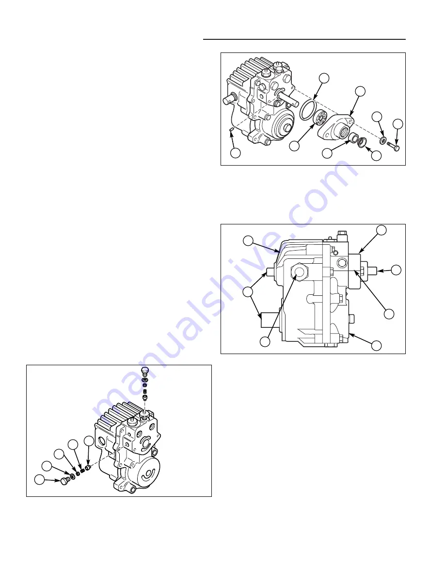
CHARGE PUMP
The charge pump with housing (E, Figure 13) must be
removed before you start the complete disassembly.
Note the orientation of the charge pump housing to end
section and either scribe a line (F) or make punch marks
to ensure proper relocation. Clean the shaft extension
(G) to remove all sharp edges, burrs, and abrasive
residue to prevent shaft seal damage.
Remove two hex head screws (A, Figure 14) and wash-
ers (B). Slide the housing assembly (C, D, E, and F) over
the shaft. Remove drive pin (G) and charge pump (H)
from shaft. Only if replacement is necessary, remove
shaft seal and bearing (C and D) from housing.
Examine the wear surfaces of pump cartridge (H, Figure
14) for excessive scratching or heavy wear patterns.
Replace both parts of this cartridge, if necessary. Do not
replace or interchange individual parts within the car-
tridge. The drive pin (G) should always be replaced.
Figure 13. Removing Charge Pump
A. Capscrew
E. Housing
B. Flat Washer
F. O-Ring
C. Lip Seal
G.
Drive Pin
D. Roller Bearing
H. Pump
F
B
H
G
E
D
C
A
CHARGE RELIEF VALVE
Remove plug (A, Figure 15) and O-ring (B), then slide
the spring (D) and poppet (E) out of the housing. Do not
alter the shims (C) if used or interchange parts with
another valve. Inspect the poppet and seat in housing for
damage and remove any foreign material in the valve
area. Replace parts as required and reinstall into hous-
ing bore.
Figure 15. Removing Charge Relief Valve
A. Plug
D. Spring
B. O-Ring
E. Poppet
C. Shim(s)
A
B
E
D
TESTING AFTER REPAIR
After repairing and reinstalling the Hydrostatic Unit, test
for proper operation.
1. Raise seat deck.
2. Remove filler cap from transmission filler tube, and
add type F Automatic Transmission Fluid until fluid is
visible (1" to 1-1/2" in the tube with engine off).
3. Replace filler cap.
Check for leaks, especially at lip seals and where
sections join together. If necessary, refer to the
Troubleshooting section of this manual and correct
malfunction.
Figure 14. U-Type Main Sections
A. Housing
E. Input Shaft
B. End Section
F. Output Shafts
C. Charge Pump Housing
G. Control Shaft
D. Scribe Location
E
C
D
B
A
C
B
C
Visually inspect bearing (D), O-ring (F), and shaft seal
(C), and replace as required. Torque screws 50-55 ft. lbs.
Not
for
Reproduction
Summary of Contents for AGCO Allis 2000 Series
Page 1: ...USE N o t f o r R e p r o d u c t i o n...
Page 18: ...1 16 1 General Information Notes N o t f o r R e p r o d u c t i o n...
Page 24: ...2 Troubleshooting Notes 2 6 N o t f o r R e p r o d u c t i o n...
Page 52: ...5 Belt Replacement Notes 5 6 N o t f o r R e p r o d u c t i o n...
Page 101: ...7 33 7 Electrical System Service Troubleshooting Notes N o t f o r R e p r o d u c t i o n...
Page 114: ...7 46 7 Electrical System Service Notes N o t f o r R e p r o d u c t i o n...
Page 126: ...8 Power Steering Service Notes 8 12 N o t f o r R e p r o d u c t i o n...
Page 162: ...11 Transaxle Removal Installation Notes 11 10 N o t f o r R e p r o d u c t i o n...
Page 206: ...13 Engine Removal Installation Notes 13 36 N o t f o r R e p r o d u c t i o n...
Page 244: ...17 Miscellaneous Component Service Notes 17 4 N o t f o r R e p r o d u c t i o n...
Page 304: ...19 Implement Lift Service Notes 19 10 N o t f o r R e p r o d u c t i o n...
Page 312: ...20 Power Steering Unit Service Notes 20 8 N o t f o r R e p r o d u c t i o n...


