TXP CLC Course
7
3
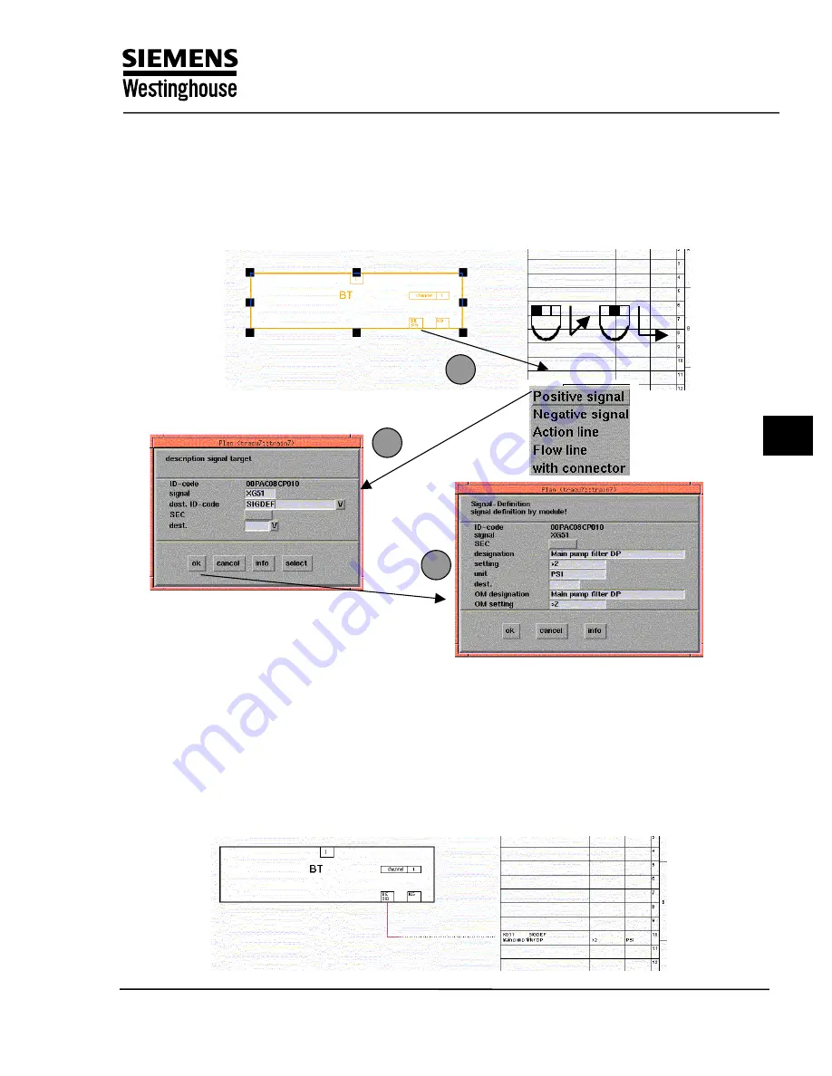
.Now you are in the process of creating a connection. Move the mouse rightwards
without pressing any buttons, until the cursor is in the output area of the function plan.
As shown in
3
.
Then press the left mouse button and hold down the middle mouse button to select
“positive signal” from the menu bar
3
4
5
4
. Now assign the SIGDEF in the pop up window as shown in
4
. Some module ports give default
“signal” (e.g. CB ON is always XB01), but this can be changed.
Select “SIGDEF” from the drop down list, and click OK. Do not enter or select any information
in the “dest.” Field.
5
. In the next mask you can give more detail about the signal. The “designation” , “setting”, and
unit fields are used to give short explanation of this signal’s function within this diagram.
Training Center
Copying of this document, and giving it to others and use or communication of the contents, are forbidden without express authority. Offenders are liable to the payment of
damages. All rights are reserved in the event of the grant of a patent or the registration of a utility model or design.
5
Summary of Contents for TXP-CLC
Page 5: ...TXP CLC Course 1 TXP Overview Training Center ...
Page 11: ...TXP CLC Course 2 Automation System AS620 Training Center ...
Page 19: ...TXP CLC Course 3 Industrial Ethernet Training Center ...
Page 29: ...TXP CLC Course 4 Engineering system ES680 Training Center ...
Page 45: ...TXP CLC Course 5 KKS Overview Training Center ...
Page 81: ...TXP CLC Course 6 Training Project Exercise 1 2 Training Center ...
Page 101: ...TXP CLC Course 7 BT Function Block Exercise 3 Training Center ...
Page 121: ...TXP CLC Course 8 AT Function Block Exercise 4 Training Center ...
Page 137: ...TXP CLC Course 9 CBO Function Block Exercise 5 Training Center ...
Page 145: ...TXP CLC Course 10 CAO Function Block Exercise 6 Training Center ...
Page 155: ...TXP CLC Course 11 DCM Function Block Exercise 7 Training Center ...
Page 187: ...TXP CLC Course 12 Generation Transfer Exercise 8 Training Center ...


