TXP-CLC
Course
2
Alternative solutions with AS 620 B (2)
Function modules (FUM) and/or Signal modules (SIM)
M
M
Field
Field
Field
Profibus
Profibus
AP
AP
FUM
FUM
FUM
FUM
FUM - Configuration
FUM - Configuration
I&C room
I&C room
I&C room
I&C room
Centralized
Centralized
Distributed
Distributed
AP
AP
JB
JB
JB
JB
SIM B
SIM B
SIM B
SIM B
SIM - Configuration
SIM - Configuration
SIM modules
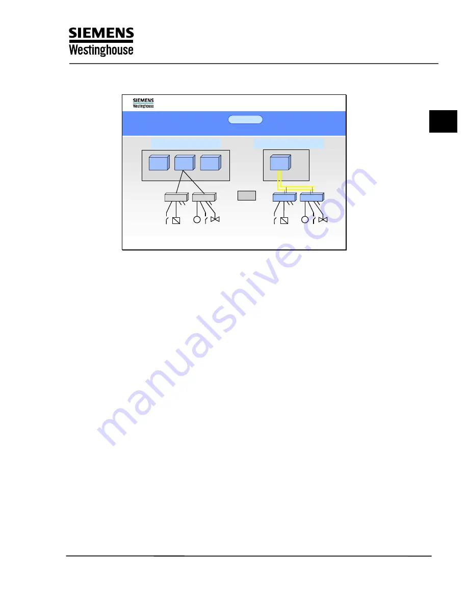
SIM modules are used for the input and output of analog and binary signals.
Their task is to digitize process signals and to output digital settings as binary or
analog signals. More complex tasks such as signal processing, monitoring, and
time-tagging are performed in the AP. A signal module in conjunction with the
associated function block performs the same function as the corresponding FUM.
SIMs are modules from the SIMATIC S5/S7, ET200 B/ET200 M range, which
allows the input and output modules to be installed locally in the process
environment instead of centrally in the automation system. For this purpose, the
modules are combined into stations and located in the immediate vicinity of the
field devices, installed in distribution boxes or wall-mounted housings for
example.
The advantage of a distributed configuration lies in the minimal space
requirements in the computer room, because only the cabinets for the AP are
installed there. Savings can also be made in wiring costs because only the loop-
in cable from the I/O to the nearest station is required.
Distributed configurations also permit the automation processors and the input
and output modules in the process environment to be located a considerable
distance apart. The SIM modules are linked with the automation processor via
PROFIBUS. PROFIBUS can be operated at a maximum data transmission rate
of 1.5 Mbit/s and is also available in a fiber-optic version for use under adverse
interference conditions or where lightning protection is required.
The flexibility of the automation system allows the FUM structure to be combined
with the distributed SIM structure, which supports the implementation of tailor-
made solutions.
Training Center
Copying of this document, and giving it to others and use or communication of the contents, are forbidden without express authority. Offenders are liable to the payment of
damages. All rights are reserved in the event of the grant of a patent or the registration of a utility model or design.
3
Summary of Contents for TXP-CLC
Page 5: ...TXP CLC Course 1 TXP Overview Training Center ...
Page 11: ...TXP CLC Course 2 Automation System AS620 Training Center ...
Page 19: ...TXP CLC Course 3 Industrial Ethernet Training Center ...
Page 29: ...TXP CLC Course 4 Engineering system ES680 Training Center ...
Page 45: ...TXP CLC Course 5 KKS Overview Training Center ...
Page 81: ...TXP CLC Course 6 Training Project Exercise 1 2 Training Center ...
Page 101: ...TXP CLC Course 7 BT Function Block Exercise 3 Training Center ...
Page 121: ...TXP CLC Course 8 AT Function Block Exercise 4 Training Center ...
Page 137: ...TXP CLC Course 9 CBO Function Block Exercise 5 Training Center ...
Page 145: ...TXP CLC Course 10 CAO Function Block Exercise 6 Training Center ...
Page 155: ...TXP CLC Course 11 DCM Function Block Exercise 7 Training Center ...
Page 187: ...TXP CLC Course 12 Generation Transfer Exercise 8 Training Center ...


