
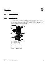


Functions
5.1 Current protection
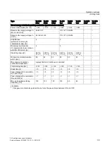
3VL molded-case circuit breakers
52
System Manual, 03/2009, 110 0110 - 02 DS 01
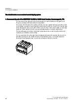
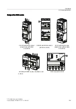
Standard features
●
Mechanical trip display:
The Reset button pops out when the RCD module trips the circuit breaker.
●
Reset button:
This must be manually reset after the circuit breaker has been tripped by the RCD module.
The circuit breaker can only be reset and switched on again after the RCD module has been
reset.
●
Cover:
Modifiable settings for ∆t and I
∆n
.
A sealable transparent cover is available for preventing modification.
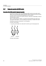
●
LED displays:
–
3 LEDs (green/yellow/red) indicate the level of the leakage/fault current. The blinking
indicator signals that the SENTRON VL RCD module is ready for operation.
–
Green: I
∆
= 25% of the set value, the cable is live
–
Green + yellow: 25% < I
∆
< 50 of the set I
∆n
value
–
Green + red: I
∆
= 50% of the set I
∆n-
value
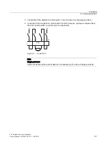
●
Test button:
The functionality of the RCD module is checked with the test button. If the test button is
pressed, differential current is simulated on a test winding attached to the summation current
converter. If it is functioning correctly, the RCD module must trip the circuit breaker.
The test button must remain pressed for at least the period of the set delay time Δt.
●
A network disconnection device:
–
makes it possible to disconnect the evaluation electronics of the RCD module from the
circuit without removing the primary cable or the busbars (e.g. before insulation tests).
–
Limitation of the maximum r.m.s. withstand voltage to an r.m.s. value of 3500 V AC for
this feature.
●
Protection function up to 50 V AC between phase and neutral conductor
●
The RCD module has a surge withstand strength of I
peak
= 2000 A. The standard surge
wave is defined as 8 / 20-µs waveform.
●
The RCD module does not trip in the case of making currents.
Δt ≥ 0 I
rms
= 3000 A
Δt ≥ 60ms I
peak
= 20 x I
n
x √2
●
The circuit breaker combination with differential current protection can be supplied from
both sides.
●
Suitable for circuit breaker standard accessories – covers, phase barriers, wire
connectors.
Summary of Contents for SENTRON 3VL series
Page 2: ......
Page 10: ...Table of contents 3VL molded case circuit breakers 10 System Manual 03 2009 110 0110 02 DS 01 ...
Page 350: ...Correction sheet 3VL molded case circuit breakers 350 System Manual 03 2009 110 0110 02 DS 01 ...
Page 358: ...Glossary 3VL molded case circuit breakers 358 System Manual 03 2009 110 0110 02 DS 01 ...
Page 359: ......


