
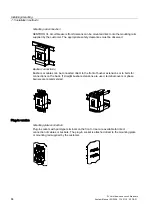

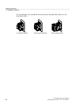


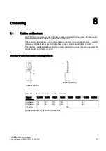

Installing/mounting
7.2 Mounting and safety clearances
3VL molded-case circuit breakers
88
System Manual, 03/2009, 110 0110 - 02 DS 01
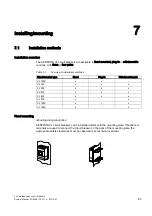
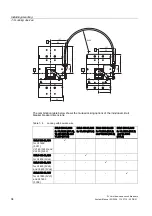
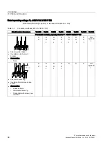
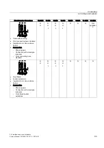
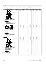
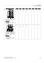
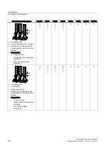
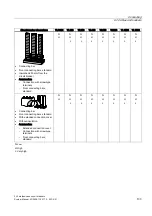
Table 7- 2
Permissible safety clearances in accordance with IEC 60947
A ≤ 415 V
A > 415-690 V
Circuit
breaker type
Switching
capacity
With or without
covers
Without covers With covers
B ≤ 690 V
C ≤ 690 V
D ≤ 690 V
VL160X
Standard High
35 mm
70 mm
35 mm
25 mm
25 mm
35 mm
VL160
Standard High
Very high
50 mm
100 mm
50 mm
25 mm
25 mm
35 mm
VL250
Standard High
Very high
50 mm
100 mm
50 mm
25 mm
25 mm
35 mm
VL400
Standard High
Very high
50 mm
100 mm
50 mm
25 mm
25 mm
35 mm
VL630
Standard High
Very high
50 mm
100 mm
50 mm
25 mm
25 mm
35 mm
VL800
Standard High
Very high
50 mm
100 mm
50 mm
25 mm
25 mm
35 mm
VL1250
Standard High
Very high
70 mm
100 mm
70 mm
30 mm
30 mm
50 mm
VL1600
Standard High
Very high
100 mm
100 mm
100 mm
100 mm
30 mm
100 mm
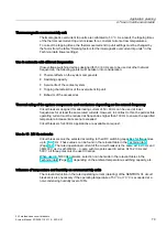
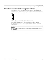
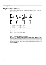
Definition of the permissible safety clearances in [mm] between
Q:
Circuit breaker and current paths (uninsulated and grounded metal)
B:
Circuit breaker phase terminal and lower panel
C:
Sides of the circuit breaker and side panels left/right (uninsulated and grounded
metal)
D:
Circuit breaker and non-conductive parts with at least 3 mm thick insulation
(insulator, insulated bar, painted plate)
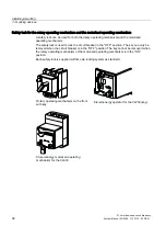
If uninsulated conductors are connected to terminals 1, 3, 5 and 7, they must be insulated
from each other independently of the direction of the mains supply (see Chapter 3.1.1.). This
can be achieved using phase barriers or terminal covers.
Terminal covers must be used for the main terminals at voltages of ≥ 600 V AC
or ≥ 500 V DC.
Note
We recommend you also insulate connections 2, 4, 6 and 8 from each other for additional
safety.
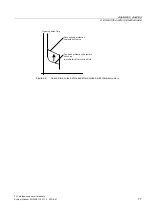
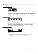
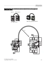
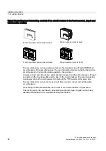
(
(
Figure 7-3
Minimum clearance between two horizontally or vertically installed circuit breakers
Summary of Contents for SENTRON 3VL series
Page 2: ......
Page 10: ...Table of contents 3VL molded case circuit breakers 10 System Manual 03 2009 110 0110 02 DS 01 ...
Page 350: ...Correction sheet 3VL molded case circuit breakers 350 System Manual 03 2009 110 0110 02 DS 01 ...
Page 358: ...Glossary 3VL molded case circuit breakers 358 System Manual 03 2009 110 0110 02 DS 01 ...
Page 359: ......


