


Circuit diagrams
3VL molded-case circuit breakers
320
System Manual, 03/2009, 110 0110 - 02 DS 01
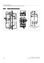
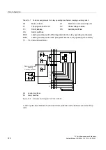
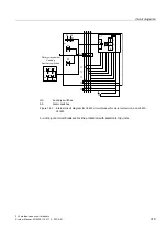
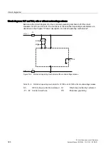
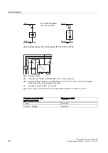
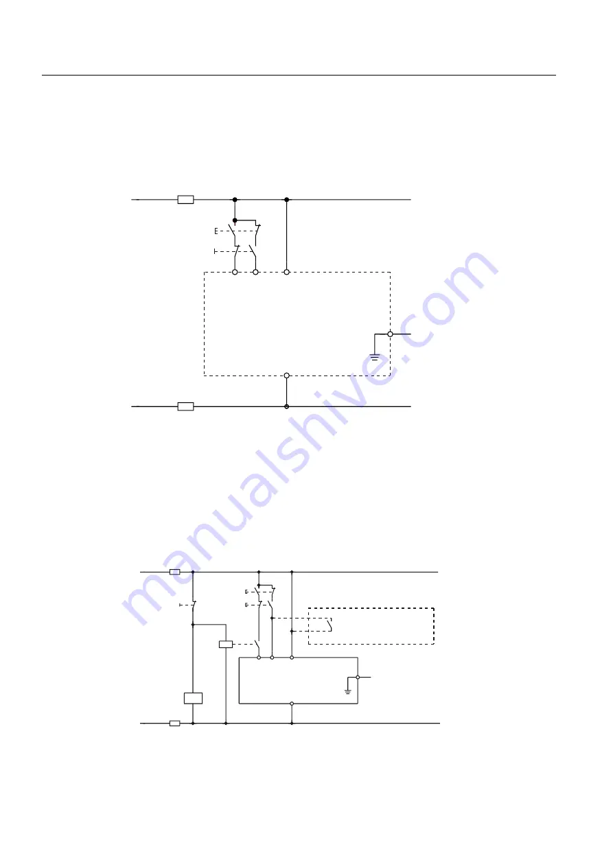
Circuit diagrams VL1 to 3, with or without undervoltage release
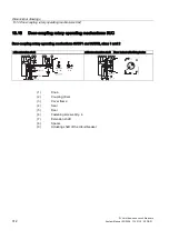
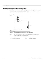
Below are the circuit diagrams for the motorized operating mechanism without stored energy
for the circuit breakers VL160X, VL160 and VL250. The functions of the motorized operating
mechanisms are described in Chapter ..........
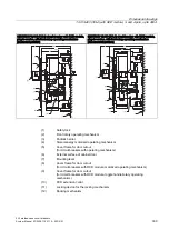
L1 (L+)
N (L2, L-)
-S1
-S0
-F1
-F2
3(
Figure 14-4 Motorized operating mechanism without undervoltage release
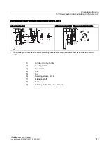
Table 14- 2 Motorized operating mechanism without stored energy for VL160X-VL250, without
undervoltage release
S0
OFF (to be provided by customer) S1
ON (to be provided by customer)
-F1, -F2 Control circuit fuse
PE
Protective grounding
621
62))
)
//
6
3(
8
1// )
.
$ODUPVZLWFKHV
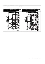
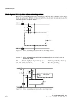
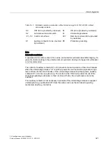
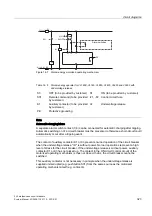
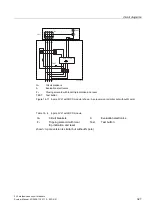
Figure 14-5 Motorized operating mechanism with undervoltage release
Summary of Contents for SENTRON 3VL series
Page 2: ......
Page 10: ...Table of contents 3VL molded case circuit breakers 10 System Manual 03 2009 110 0110 02 DS 01 ...
Page 350: ...Correction sheet 3VL molded case circuit breakers 350 System Manual 03 2009 110 0110 02 DS 01 ...
Page 358: ...Glossary 3VL molded case circuit breakers 358 System Manual 03 2009 110 0110 02 DS 01 ...
Page 359: ......