


Circuit diagrams
3VL molded-case circuit breakers
322
System Manual, 03/2009, 110 0110 - 02 DS 01
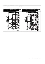
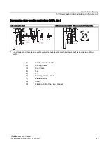
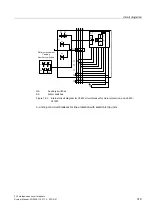
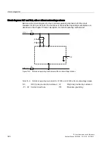
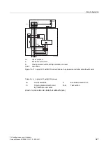
Circuit diagrams VL1 to 6, with or without undervoltage release
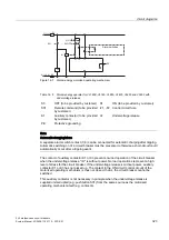
Below are the circuit diagrams for the stored-energy motorized operating mechanism for the
circuit breakers VL160X, VL160, VL250, VL400, VL630 and VL800. The functions of the
motorized operating mechanisms are described in Chapter ..........
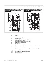
L1 (L+)
N (L2, L-)
-S1
-S0
-F1
-F2
3(
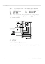
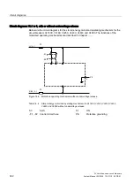
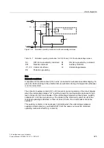
Figure 14-6 Motorized operating mechanism without undervoltage release
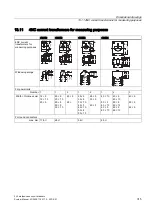
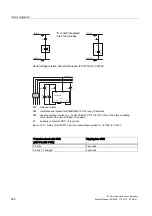
Table 14- 4 Stored-energy motorized operating mechanism for VL160X, VL160, VL250, VL400,
VL630 and VL800 without undervoltage release
S0
AUS
S1
ON
-F1, -F2 Control circuit fuse
PE
Protective grounding
Summary of Contents for SENTRON 3VL series
Page 2: ......
Page 10: ...Table of contents 3VL molded case circuit breakers 10 System Manual 03 2009 110 0110 02 DS 01 ...
Page 350: ...Correction sheet 3VL molded case circuit breakers 350 System Manual 03 2009 110 0110 02 DS 01 ...
Page 358: ...Glossary 3VL molded case circuit breakers 358 System Manual 03 2009 110 0110 02 DS 01 ...
Page 359: ......


