background image

Chapter 6

CPE Management Interface

RUGGEDCOM WiN5100/WiN5200

User Guide

60

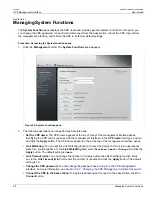
Managing the Secondary Memory Bank

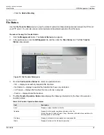
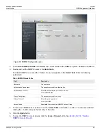
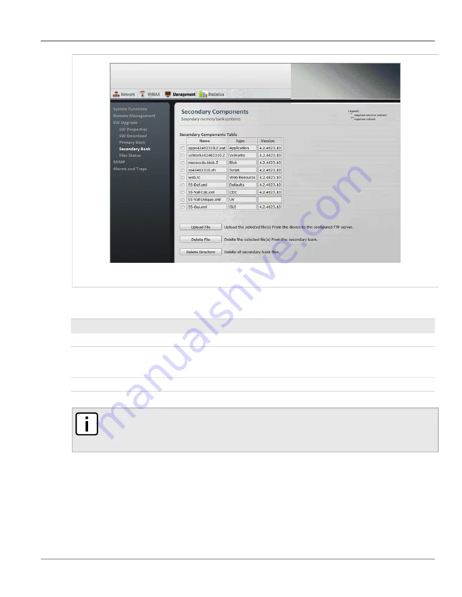
Figure 52: Secondary Bank Components pane

3. The 

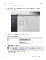
Secondary Components Table

 displays the following information:

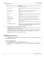
Table: Secondary Components Table

Field

Description

Name

Displays the software component filename.

Type

Displays the software component file type.
Values: Package | Application | VxWorks | Blob | Script | WebResource | Defaults | CDC

| Regulation | UV | GUI

Version

Displays the software component version number.

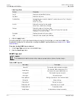
4. To upload a file to your FTP server:

NOTE

Before uploading files to an FTP server, you must configure an FTP server on the 

FTP

Server Properties

 pane. For instructions on how to configure the FTP server properties, see

Section 6.2.8.3, “Downloading CPE Software”

.

• Select a file from the 

Secondary Components Table

.

• Click the 

Upload File

.

5. To delete a file:

• Select a file from the 

Secondary Components Table

.

• Click the 

Delete File

.

6. To delete all files:

Summary of Contents for RUGGEDCOM WiN5100

Page 1: ... And Cautions Introduction 1 Product Description 2 Mounting 3 Installation Procedure 4 Equipment Configuration and Monitoring 5 CPE Management Interface 6 WiN5100 WiN5200 Specifications A IDU to ODU Cable Specifications B List of Acronyms C RUGGEDCOM CPE Warranty D ...

Page 2: ...RUGGEDCOM WiN5100 WiN5200 User Guide ii ...

Page 3: ...ystem 3 1 4 Allowed Antenna Types 3 Chapter 2 Product Description 5 2 1 IEEE 802 16e Mobile WiMAX Compliance 5 2 2 Block Diagram 5 2 3 Features 7 2 3 1 Mobile WiMAX Wave 2 MIMO Features 7 2 3 1 1 Space Time Coding 8 2 3 1 2 Time Division Duplexing TDD 9 2 3 1 3 Coding Rate 9 2 3 1 4 Modulation 9 2 3 1 5 Convolution Turbo Coding Correction 9 2 3 2 Deployment Models 9 2 3 2 1 PTP Deployment 9 2 3 2 ...

Page 4: ...s 22 4 5 Mounting Bracket Installation 22 4 6 Pole Mount Installation 24 4 7 Wall Mount Installation 25 4 8 Connecting the Ground Cable 27 4 9 Aligning the CPE Antenna 27 4 10 Cable Connections 28 4 10 1 Weatherproofing 28 4 10 1 1 Weatherproofing Cable Connections 28 4 10 2 Assembling the RJ45 Connector 30 4 10 3 Installing the WiN1010 Data Adaptor 34 4 10 4 WiN1010 Data Adaptor LED Indicators 35...

Page 5: ...6 2 8 3 Downloading CPE Software 56 6 2 8 4 Managing the Primary Memory Bank 57 6 2 8 5 Managing the Secondary Memory Bank 59 6 2 8 6 File Status 61 6 2 9 SNMP Administration 62 6 2 9 1 SNMP General Settings 62 6 2 9 2 SNMPv2 Configuration 63 6 2 9 3 SNMPv3 Configuration 64 6 2 9 4 Viewing SNMPv3 Access Groups 66 6 2 9 5 MIB2 System 66 6 2 10 Alarms Traps 67 6 2 11 NTP Server 71 6 2 12 Developer M...

Page 6: ...ethod 88 6 5 2 2 Configuring EAP TLS Authentication 89 6 5 2 3 Configuring EAP TTLS Authentication 90 6 5 2 4 Configuring Null Authentication 91 6 5 2 5 Loading Authentication Certificates 91 6 5 3 Viewing Base Station Information 92 6 5 4 Configuring WiMAX Radio Parameters 93 Appendix A WiN5100 WiN5200 Specifications 95 Appendix B IDU to ODU Cable Specifications 99 Appendix C List of Acronyms 101...

Page 7: ...se the user will be required to correct the interference at his own expense CAUTION Caution Service This product contains no user serviceable parts Attempted service by unauthorized personnel shall render all warranties null and void Changes or modifications not expressly approved by RUGGEDCOM could invalidate specifications test results and agency approvals and void the user s authority to operat...

Page 8: ...RUGGEDCOM WiN5100 WiN5200 User Guide FCC Statement And Cautions viii ...

Page 9: ...This manual assumes that users have some experience with WiMAX technologies and procedures NOTE While some safety precautions are reviewed here this guide assumes that installers are trained in safe installation practises Users who are new to WiMAX technologies and service procedures should not rely on this guide for comprehensive guidance Section 1 1 WiN5100 with External Antenna Package Componen...

Page 10: ... and public areas Section 1 3 2 Lightning Protection When the ODU CPE is installed in an outdoor location all indoor components Ethernet connections and power supply should be connected through a lightning protector Lightning protection is intended to protect people and equipment located indoors from lightning that might strike the ODU CPE or its outdoor cables The lightning protection device shou...

Page 11: ...er e i r p is not more than that necessary for successful communication This radio transmitter WIN5149 AC WIN5149 DC WIN5249 WIN5158 AC WIN5158 DC WIN5258 has been approved by Industry Canada to operate with the antenna types listed below with the maximum permissible gain and required antenna impedance for each antenna type indicated Antenna types not included in this list having a gain greater th...

Page 12: ...le Antenna Types Type Manufacturer Model Number Gain Impedance Dual slant antenna MTI Wireless Edge Ltd MT 465017 SVH E 22 5 dBi 50Ω Dual slant antenna MTI Wireless Edge Ltd MT 465017 NVH 22 5 dBi 50Ω Omnidirectional MTI Wireless Edge Ltd MT 462008 N A 9 5 dBi 50Ω Omnidirectional HUBER SUHNER SWA 0860 360 4 0 V_2 1399 17 0099 9 5 dBi 50Ω For WCS CPE 2 3GHz to comply with FCC regulations and restri...

Page 13: ...x deux conditions suivantes l appareil ne doit pas produire de brouillage et l utilisateur de l appareil doit accepter tout brouillage radio électrique subi meme si le brouillage est susceptible d en compromettre le fonctionnement Section 2 1 IEEE 802 16e Mobile WiMAX Compliance The IEEE 802 16 2005 specifications describe a PMP broadband wireless access standard for systems This standard includes...

Page 14: ...rom the Base Band modem to the high frequency RF output Several RF modules exist each supporting a different frequency band 4 Chassis 5 Antenna or Antennas dual omni or polarization antennas WiN5100 or integrated dual polarization antenna WiN5200 supporting MIMO schemes Figure 1 WiN5100 CPE Block Diagram External Antennas Figure 2 WiN5200 CPE Block Diagram Integrated Antenna ...

Page 15: ...received signals has the immediate benefit of improving received signal strength but MIMO also enables transmission of parallel data streams for greater throughput For example in a 2 2 MIMO two transmit and two receive elements dual polarization point to point system the carrier s allocated frequency can be used twice effectively doubling the throughput data rate In point to multipoint systems emp...

Page 16: ...direction to provide spatial diversity to enhance the signal quality to a specific subscriber located anywhere within the range of the antenna beam Although providing less signal gain than beam forming transmit diversity is more robust for mobile users as it does not require prior knowledge of the path characteristics of a subscriber s particular frequency channel One such STC technique known as t...

Page 17: ... coding rate is the ratio of user data to the total data transmitted including the redundant error correction data The base station supports coding rates of 1 2 2 3 and 3 4 Section 2 3 1 4 Modulation The modulation technique specifies how the data is coded within the OFDMA carriers The base station supports QPSK 16 Quadarature Amplitude Modulation QAM and 64 QAM modulations Section 2 3 1 5 Convolu...

Page 18: ...ance with local regulation requirements The CPE divides the available frequency band into channels Allocation of channels during deployment is dependent on spectrum availability in the licensed band and local licensing requirements and conditions Channel selection allows planners to obtain the maximum geographic coverage while avoiding frequency contention in adjacent sectors Section 2 3 3 Service...

Page 19: ...ransfer requirement Typical applications include streaming MPEG video or VOIP with silence suppression This is efficient for applications that have a real time component and continuously changing bandwidth requirements Extended Real Time Polling Service ert PS The base station schedules a continuous series of transmit opportunities for the subscriber to send variable size data packets This schedul...

Page 20: ...2 Product Description RUGGEDCOM WiN5100 WiN5200 User Guide 12 Physical Description Section 2 3 4 Physical Description Dimensions H W D without antenna 22cm 9 2cm 6cm Weight 1 5 Kg Figure 4 WiN5100 General View ...

Page 21: ...N5200 User Guide Chapter 2 Product Description Connectors and LED Indicators 13 Figure 5 WiN5200 Top View Section 2 3 5 Connectors and LED Indicators Connectors and LED indicators are found on the bottom of the CPE casing ...

Page 22: ...Connectors AC Version Section 2 3 5 1 WiN5100 Connectors AC Version Figure 6 WiN5100 Connectors AC Version Table WiN5100 Connectors AC Version Name Description Connector Type ETH PWR Data and power from PoE injector RJ 45 Ground Grounding screw ANT1 Antenna 1 RF ANT2 Antenna 2 RF ...

Page 23: ... Section 2 3 5 2 WiN5100 Connectors DC Version Figure 7 WiN5100 Connectors DC Version Table WiN5100 Connectors DC Version Name Description Connector Type ETH PWR Ethernet data connection only RJ 45 Ground Grounding screw ANT1 Antenna 1 RF ANT2 Antenna 2 RF DC DC input 10 VDC to 30 VDC 3 pin connector ...

Page 24: ...round Grounding screw Section 2 3 6 LED Indicators The LED indicators at the bottom of the CPE casing display the following information RSSI displays the RSSI level W LNK displays the wireless link indication PWR displays the power status Table CPE LED Indicators LED Color Description WLNK is ON Green CPE is connected with and receives services from the base station network entry is complete WLNK ...

Page 25: ...SSI 90 RSSI two LEDs are ON Green 85 RSSI 90 RSSI three LEDs are ON Green 80 RSSI 85 RSSI four LEDs are ON Green 75 RSSI 80 RSSI five LEDs are ON Green 70 RSSI 75 RSSI six LEDs are ON Green 65 RSSI 70 RSSI seven LEDs are ON Older Hardware LEDs 1 7 Green LED 8 Red Latest Hardware LEDs 1 6 Green LED 7 Red 20 RSSI 60 RSSI only the last LED is ON most significant Red 20 RSSI Saturation ...

Page 26: ...RUGGEDCOM WiN5100 WiN5200 User Guide Chapter 2 Product Description LED Indicators 18 ...

Page 27: ...ite survey should include a detailed planning of the WiMAX system deployment The system deployment plan should include mounting points and the routes for the power and backhaul cables Section 3 1 1 Recommended Site Requirements It is highly recommended that the WiN5100 WiN5200 CPEs be mounted near the edge of the roof of a tall building The CPEs should be pointed in the direction of the area to be...

Page 28: ...RUGGEDCOM WiN5100 WiN5200 User Guide Chapter 3 Mounting Wall Mounting 20 ...

Page 29: ... antenna installation observe the following For WiN5149 WiN5249 and WiN5158 WiN5258 always install the antenna at least 0 65 m from people and public areas For other models always install the antenna at least 0 39 m from people and public areas Antenna must be in a fixed position After it is installed do not change the antenna position Section 4 2 Required Installation Tools Flat screwdriver Wrenc...

Page 30: ...ovided or approved by Siemens Must not be longer than 80 m 262 ft Must be ground as shown in Figure 9 Solder Figure 9 Cat5 Cable Grounded Section 4 5 Mounting Bracket Installation The following procedures describe how to secure the mounting bracket to the CPE unit Procedure Securing the Mounting Bracket to the Antenna 1 Place the antenna enclosure base bracket against the back of the antenna Make ...

Page 31: ...ntenna enclosure base bracket to the antenna using nuts washers and spring washers Make sure the nuts are torqued to 24 Nm 17 7 ft lb Procedure Securing the Mounting Bracket to the Enclosure 1 Place the antenna enclosure base bracket against the back of the enclosure Make sure it is oriented with the elevation axis Figure 11 Mounting Bracket to Enclosure Assembly ...

Page 32: ...CPE unit to a pole NOTE When mounting a WiN5258 or WiN5249 unit make sure that the antenna and CPE unit are rotated by 45 degrees when compared to other models with the arrow on the antenna facing up as shown in the following figure Figure 12 Mounting a WiN5258 or 5249 Unit Procedure Mounting the CPE Unit To a Pole 1 Select a mounting location on the pole 2 Position the mounting bracket against th...

Page 33: ...igure 13 Mounting the Antenna Enclosure to a Pole 4 Adjust the position of the CPE unit For more information about how to align the CPE Antenna refer to Section 4 9 Aligning the CPE Antenna 5 Tighten the screws connecting the clamping bracket to the mounting bracket Make sure the screws are torqued to 14 Nm 10 ft lb Section 4 7 Wall Mount Installation To following procedure describes how to mount ...

Page 34: ... Place the mounting bracket on the wall and mark 4 mounting holes 3 Drill 4 holes and insert 4 type NC 1 4 fastening inserts into the holes 4 Secure the mounting bracket to the wall with 4 type NS 1 4 1 2 HEX screws 4 spring washers and 4 flat washers 5 Connect the arm bracket to the mounting bracket using a screw spring washer and washer Make sure the screw is hand tightened 6 Connect the CPE uni...

Page 35: ...ation improve link quality by changing the direction of the antenna or by placing the CPE at a higher or alternate location 4 Rotate the CPE until the maximum RSSI link quality reading is achieved If you encounter prolonged difficulty in achieving the expected link quality try to improve the reception quality by placing the CPE at a higher point or in an alternate location NOTE Ensure that the fro...

Page 36: ...ofing Cable Connections Most outdoor unit antenna or cable problems are caused by coaxial cable connections loosened by vibration allowing moisture to penetrate the connector interface We recommend that all outdoor unit to cable connections be weatherproofed using a procedure similar to the one described below This method of weatherproofing must be completed on all external connections including R...

Page 37: ...f amalgamating Tape 2 Tightly wrap the connector and the cable Overlap the tape without gaps all the way along the connector Continue wrapping the tape 25 mm 1 onto the cable Figure 16 Wrapping the Cable with Rubber splicing or Self amalgamating Tape 3 For UV protection of the rubber splicing tape wrap two layers of electrical tape on top of the rubber splicing tape ...

Page 38: ...ection 4 10 2 Assembling the RJ45 Connector The ODU CPE uses a male shielded RJ45 connector to provide the data and Power over Ethernet PoE connection to the device To assemble the RJ45 connector follow the instructions in this section Before beginning you will need the following items CPE RJ45 Connector Kit Category 5e cable of suitable length for your application for information on cable specifi...

Page 39: ...igure 20 and Figure 21 Strip at least 22mm 0 71 inch of sheathing from the end of the cable Remove the inner jacket and foil leaving 10mm 0 25 inch of inner jacket and the drain wire Fan the pairs into the proper color code and trim the conductors leaving 12mm 0 47 inch extending from the inner jacket Figure 20 Preparing the CPE Cable Figure 21 Pin Arrangement ...

Page 40: ...TP1 7 RTN TP3 8 RTN TP3 3 Refer to Figure 23 Using the supplied RJ45 connector use an abrasive to remove the nickel coating on the grounding shield Figure 23 Preparing the RJ45 connector 4 Refer to Figure 24 Place the RJ45 connector over the wire ends making sure to maintain the pin arrangement shown in Figure 21 Once inserted visually inspect the cable layout Crimp the RJ45 connector to the cable...

Page 41: ...in wire Figure 25 Solder the Drain Wire 6 Refer to Figure 26 Insert the modular plug into the plug housing Align the latch with the LATCH slot Press the modular plug into the plug housing until it bottoms out Figure 26 Assembly of Connector Components 7 Refer to Figure 27 While maintaining inward pressure on the plug or keeping the dust cover engaged tighten the compression nut to 0 56Nm 5 In lbs ...

Page 42: ...onnector provides 10 100 Base T data and power to the outdoor unit over a Category 5e cable This cable provides for the bi directional transfer of data and signalling as well as a power feed to the outdoor equipment NOTE The Category 5e Ethernet cable is not included Refer to Appendix B IDU to ODU Cable Specifications for detailed technical specifications Figure 28 Power over Ethernet Connection S...

Page 43: ... WARNING EXPLOSION HAZARD Substitution of components may impair suitability for Class I Division 2 Do not disconnect equipment unless power has been switched off or the area is known to be non hazardous Use only Lambda DPP240 48 1 Power Supply in conjunction with the unit RISQUE D EXPLOSION La substitution decomposants peut rendre ce matériel inacceptable pour les emplacements de Classe I Division...

Page 44: ...PoE injector Data Power jack and the CPE 3 Connect a Category 5e cable between the Ethernet switch and the PoE injector Data jack 4 Connect the AC open ended cable to the PSU Figure 30 Complete Class 1 Division 2 Installation Kit CAUTION The power supply AC cord should be 3 wires 18 AWG minimum with a length of less than 4 5 m and safety certified according to national rules ...

Page 45: ...network parameters for other operating systems refer to your operating system documentation Before beginning ensure that the CPE is connected to the Power over Ethernet PoE power adaptor and that power is applied Procedure Connecting a computer to the CPE 1 Ensure that the PoE adaptor is connected to the base station Connect the computer s Ethernet port to the PoE adaptor s Ethernet port 2 On the ...

Page 46: ...tocol TCP IP Properties dialog click OK On the Local Area Connection Properties dialog click Close 8 Launch your web browser and type https 192 168 254 251 in the address field NOTE For information on browser versions and compatibility refer to the release notes for your software version 9 Press Enter The Login window appears 10 Enter your user name and password and click Log In The RUGGEDCOM WiN5...

Page 47: ...PE configure additional parameters remotely through the wireless link Procedure Configuring the WiN5100 WiN5200 1 Connect a computer to the CPE and log in to the CPE management interface For instructions see Section 5 1 Connecting to and Logging In to the CPE 2 Click the WiMAX button The Scanner Settings pane appears Figure 34 Scanner Settings pane 3 Review the entries in the Scanner Table and ens...

Page 48: ...atch the base station configuration 5 To remove a row from the table select the row and click the button The row is removed from the table 6 After making changes to the Scanner Settings table click the Apply button 7 To begin transmitting click the Connect button 8 Click the Network button The IP Settings pane appears Figure 35 IP Settings pane 9 Configure the CPE IP addresses in the following fie...

Page 49: ...anged the Configured LAN IP Address or Configured LAN Mask fields reboot the CPE a Click the Management button The System Functions pane appears b Click the Reboot button The CPE reboots 12 Review the CPE statistics and ensure that the CPE is operational Click the Statistics button The General Statistics pane appears Figure 36 General Statistics pane 13 Confirm that the CPE Status field indicates ...

Page 50: ...WiN5100 WiN5200 User Guide 42 Configuring the CPE Figure 37 Service Flow pane 15 Log out of the CPE management interface Click the Management button The System Functions pane appears 16 Click the Logout button You are logged out of the CPE management interface ...

Page 51: ...terface through the CPE s LAN or RF IP address Section 6 1 Using the CPE Management Interface The CPE management interface consists of four main areas Configuration Buttons a set of buttons providing access to configuration options To select a group of configuration options click a button Options Pane a set of links providing access to individual configuration panes To select a specific configurat...

Page 52: ...n groups of configuration options Clicking a button displays a set of links in the Options Pane Clicking a link in the options pane displays a pane where you can review and configure system parameters or review system data Figure 39 CPE Configuration Buttons Table Configuration Buttons and Options Pane Links Configuration Button Description Option Pane Links Network Access to CPE network settings ...

Page 53: ... to manage general system functions See Section 6 2 1 Managing System Functions change the management interface password See Section 6 2 2 Changing the CPE Management Interface Password manage CPE users and access levels See Section 6 2 3 Users and Access Levels configure the syslog parameters See Section 6 2 6 Log Management configure the remote management parameters See Section 6 2 7 Remote Mana...

Page 54: ...unit as you work with the management interface In the CPE name field type a name and click the Apply button The CPE name appears in the at the top of the management interface panes Link Watchdog You can set the Link Watchdog function to reset the device if it is not in an operational state for a continuous time In the Link WatchDog field select Disabled Smart or Always and click the Apply button T...

Page 55: ...CPE to its factory default settings except for parameters that affect CPE connectivity and reboot the CPE click the Set Partial Defaults button Section 6 2 2 Changing the CPE Management Interface Password The Change Password for User Admin pane appears when you click the Change Password button on the System Functions pane On this pane you can change the the CPE management interface password for th...

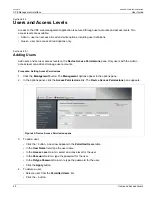
Page 56: ...min access level can add and manage user accounts Procedure Setting Access Permissions 1 Click the Management button The Management options appear in the options pane 2 In the options panel click the Access Permissions link The Device Access Permissions pane appears Figure 42 Device Access Permissions pane 3 To add a user Click the button A new row appears in the Permitted Users table In the User ...

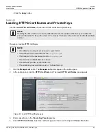
Page 57: ...e Loading HTTPS Certificates NOTE All certificates and keys must be saved in pem format The filename for the certificate must be httpscert pem The filename for the private key must be httpskey pem The maximum certificate file size is 20 kb The maximum private key file size is 4 kb The private key password can be up to 16 characters long 1 Click the Management button The Management options appear i...

Page 58: ...k Start button The Quick Start Settings pane appears b Click the Reboot button Section 6 2 5 Generating SSH Keys Use the SSH Keys pane to reboot the base station and generate new SSH keys Procedure SSH Keys 1 Click the Management button The Management options appear in the options pane 2 In the options panel click the SSH Keys link The SSH Keys pane appears Figure 44 SSH Keys pane NOTE Key generat...

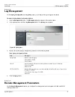
Page 59: ...tion parameters in the following fields Table Syslog Configuration Fields Field Description Syslog Enable Enables or disables logging Values Enable Disable Default Disable Server IP Sets the IP address of the server to which log files are uploaded Type an IPv4 address Values IPv4 address Default 0 0 0 0 UDP Port 1 65535 Sets the UDP port on the server to use when uploading the log files to the ser...

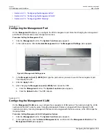
Page 60: ...35 field type the port number you want to use for the management port The default port is 80 4 Click the Apply button 5 After changing the Management port 1 65535 field reboot the CPE a Click the Management button The System Functions pane appears b Click the Reboot button The CPE reboots Section 6 2 7 2 Configuring the Management VLAN On the Management VLAN pane you configure the management VLAN ...

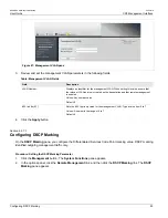
Page 61: ...enabled Values Any numeric value Default 0 802 1p bits 0 7 Sets the 802 1p priority value for the management VLAN Type a value from 0 to 7 Values A number in the range of 0 to 7 Default 6 4 Click the Apply button Section 6 2 7 3 Configuring DSCP Marking On the DSCP Marking pane you configure the Differentiated Services Code Point marking value DSCP marking identified outgoing management traffic on...

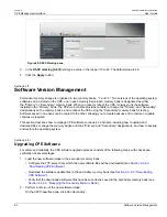
Page 62: ...o the other allowing you to create backups and to restore or update versions as required This section describes how to manage CPE software versions 4 2 and later including how to upload and download files manage the memory banks and their Primary and Secondary designations and how to backup and restore the operating system Section 6 2 8 1 Upgrading CPE Software For safety and reliability the CPE s...

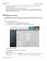
Page 63: ...y to be run by default on bootup Section 6 2 8 2 Viewing Software Properties The SW Properties pane displays information about the software loaded into each CPE memory bank On this pane you can reboot the CPE from the secondary bank set the current bank as the primary bank and reboot the CPE Procedure Viewing software properties 1 Click the Management button The System Functions pane appears 2 In ...

Page 64: ...UV Displays the filename of the UV Unique Value configuration file in the Primary memory bank Configuration Changes Counter Displays the number of changes made to configuration values on the CPE This value only includes changes to configuration values It does not include events such as setting the primary software image or uploading a file 4 The following operations can be performed from this pane...

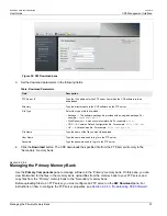
Page 65: ... A Unique Value file For example BS Val Unique xml File Name Type the name of the file you want to download User Name Type the user name used to log in to the FTP server Password Type the password used to log in to the FTP server 4 Click the Download button The CPE downloads the specified file from the FTP server directory to the Secondary memory bank Section 6 2 8 4 Managing the Primary Memory Ba...

Page 66: ...Primary Components Table Field Description Name Displays the software component filename Type Displays the software component file type Values Package Application VxWorks Blob Script WebResource Defaults CDC Regulation UV GUI Version Displays the software component version number 4 To upload a file to your FTP server NOTE Before uploading files to an FTP server you must configure an FTP server on ...

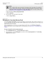
Page 67: ... the Copy directory Section 6 2 8 5 Managing the Secondary Memory Bank Use the Secondary Components pane to manage software in the Secondary memory bank On this pane you can view information for the files in the memory bank upload files from the memory bank to your FTP server and delete files from the memory bank Before uploading files to an FTP server you must configure an FTP server on the FTP S...

Page 68: ...age Application VxWorks Blob Script WebResource Defaults CDC Regulation UV GUI Version Displays the software component version number 4 To upload a file to your FTP server NOTE Before uploading files to an FTP server you must configure an FTP server on the FTP Server Properties pane For instructions on how to configure the FTP server properties see Section 6 2 8 3 Downloading CPE Software Select a...

Page 69: ...e Operation Status list select an operation status OK displays successfully completed file transfers Not Started displays requested file transfers that have not yet started In Process displays file transfers that are currently in progress Failure displays failed file transfers 4 The File Transfer Operation Status table displays the following information for the files in the selected operation stat...

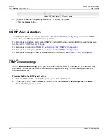
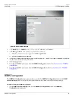
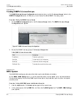
Page 70: ...Settings For instructions on configuring SNMPv2 see Section 6 2 9 2 SNMPv2 Configuration For instructions on configuring SNMPv3 see Section 6 2 9 3 SNMPv3 Configuration For instructions on setting the MIB2 system identification information see Section 6 2 9 5 MIB2 System Section 6 2 9 1 SNMP General Settings On the SNMP General Settings pane you can enable or disable SNMPv2 and SNMPv3 set the SNMP...

Page 71: ...utton removes the last entry in the table 6 Click the Apply button 7 To configure SNMPv2 parameters click the SNMPv2 Configuration button See Section 6 2 9 2 SNMPv2 Configuration 8 To configure SNMPv3 parameters click the SMPv3 Configuration button See Section 6 2 9 3 SNMPv3 Configuration Section 6 2 9 2 SNMPv2 Configuration The SNMPv2c Configuration pane appears when you click the SNMPv2 Configur...

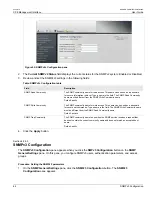
Page 72: ...MP community name for write access This name can be used as a password for secure set commands Type a name in the field The SNMP Write Community name must be different from the SNMP Read Community name Default private SNMP Trap Community The SNMP community name to use when the SNMP service receives a request that does not contain the correct community name and does not match an accepted host name ...

Page 73: ...rname The user name Authentication Passphrase The passphrase used for authentication Authentication Protocol Select the authentication protocol for the user Value HMAC SHA1 Privacy Passphrase The passphrase used for privacy Privacy Protocol Select the privacy protocol Value CBC DES Access Group Associated the user with an SNMPv3 Access Group 4 To remove an SNMPv3 user select a row in the Users Tab...

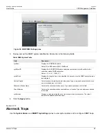
Page 74: ...NMPv3 Access Groups table Field Description Group Name The access group name Read View The read view for the access group Write View The write view for the access group Notification View The notification view for the access group Section 6 2 9 5 MIB2 System The SNMP MIB2 settings provide subscriber station system identification information On the SNMP MIB2 Settings pane you set the subscriber stat...

Page 75: ... time in hundredths of a second since the SNMP subsystem was last initialized Contact Details Contains subscriber station contact information Type a name and contact details such as an e mail address in this field Subscriber Station Name Contains the subscriber station name Type a descriptive name in this field Street Address Contains the subscriber station street address or location Type and addr...

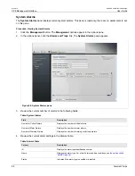
Page 76: ...59 System Alarms pane 3 Review the current number of alarms in the following fields Table System Alarms Field Description Number of Critical Alarms Displays the number of critical alarms Number of Major Alarms Displays the number of major alarms Number of Warning Alarms Displays the number of warning or advisory alarms 4 Review the current alarm settings in the Alarms Table Table Alarms Table Colu...

Page 77: ...e most recent alarm SNMP Trap Settings On the SNMP Trap Settings panel configure the subscriber station SNMP traps From this pane you can also select traps and send them on demand NOTE To send traps you must have SNMP Trap Destinations configured For instructions on configuring SNMP Trap Destinations see Section 6 2 9 SNMP Administration Procedure Setting SNMP traps 1 Click the Management button T...

Page 78: ...traps on demand To send traps you must have SNMP Trap Destinations configured For instructions on configuring SNMP Trap Destinations see Section 6 2 9 SNMP Administration Procedure Sending SNMP traps on demand 1 In the Traps Table select one or more SNMP traps 2 Click the Send Trap button SNMP Traps List NOTE The WIMAX SS TRAPS mib file in the software release folder contains a full list of traps ...

Page 79: ...g sent at the occurence the trap will be sent every 1000 packets Section 6 2 11 NTP Server Use the NTP Server pane to access the NTP server NOTE Prior to enabling the NTP server the Time Advertisement Enabled field must be set on the GPS pane in the base station This field enables the NTP Server to work properly Procedure Accessing the NTP Server 1 Click the Management button The Management option...

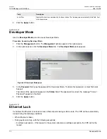
Page 80: ...oper Mode link The Developer Mode pane appears Figure 62 Developer Mode pane 3 In the Password field type the password for Developer Mode To obtain this password contact Technical Support The status of the password appears in the Status field If the password is correct the message Correct Password appears in this field 4 Click the Apply button Section 6 2 13 Ethernet Lock If enabled the Ethernet L...

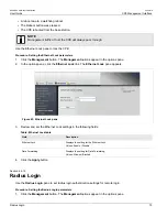
Page 81: ...ptions pane click the Ethernet Lock link The Ethernet Lock pane appears Figure 63 Ethernet Lock pane 3 Review and set the Ethernet Lock settings in the following fields Table Ethernet Lock table Field Description Ethernet Lock Displays the setting for the Ethernet Lock Values Enable Disable Data Forwarding Displays the setting for Data Forwarding Values Allowed Blocked 4 Click the Apply button Sec...

Page 82: ... IP Address Type an IP address in this field Login AAA Port The configured Web Login AAA Server Port Type a value in this field Login AAA Secret The configured Web Login AAA Server Secret Type a value in this field NAS ID The Radius NAS Identifier Type a value in this field 4 Click the Apply button Section 6 3 CPE Network Configuration This section describes how to set the CPE LAN and RF IP settin...

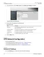
Page 83: ...ield you must reboot the CPE Current LAN Mask Displays the currently configured LAN netmask Configured LAN Mask To change the LAN mask type a dotted decimal mask in this field After changing this field you must reboot the CPE RF IP mode Displays the RF IP mode Static or DHCP To change the mode select a value from the list RF IP Address Displays the RF IP address To change the address type an IPv4 ...

Page 84: ...d with the configured VLAN number and priority Incoming management frames must be tagged with the same values or the CPE drops the incoming frames Procedure Setting the VLAN Tagging Parameters 1 Click the Network button The IP Settings pane appears 2 In the options panel click the Ethernet Settings link The VLAN Tagging pane appears Figure 66 VLAN Tagging pane 3 View and configure the LAN and RF I...

Page 85: ...an set the MAC address aging time and clear the MAC Address Table Procedure Managing the the MAC Address Table 1 Click the Network button The IP Settings pane appears 2 In the options panel click the Ethernet Settings link and then click the MAC Address Table link The MAC Address Table pane appears Figure 67 MAC Address Table pane 3 In the Aging time 300 1800 sec field set the MAC address aging ti...

Page 86: ... address of the base station itself 5 To remove an entry from the MAC address table select a row in the table and click the Clear button 6 After changing the Aging time 300 1800 sec field click the Apply button Section 6 3 2 3 MTU Configuration On the MTU pane you can enable or disable the maximum transmission unit The MTU specifies the size of the largest data unit in bytes that the Base Station ...

Page 87: ...ions appear in the options pane 2 In the options pane click the Access List link The Access List pane appears Figure 69 Access List pane 3 Review and set the Access List settings in the following fields Table Access List Configuration table Field Description Access List Displays the setting for the Access List Values Enable Disable Total Number of Entries Type a number in the field Max Number of S...

Page 88: ... button If no rows are selected clicking the button removes the last entry in the table 7 Click the Apply button Section 6 4 CPE Statistics This section describes how to view general CPE system statistics See Section 6 4 1 General Statistics view CPE hardware information See Section 6 4 2 Device Info view and clear CPE RF statistics See Section 6 4 3 RF Statistics view and clear network statistics...

Page 89: ...ation MAC address CPE Status Displays the current CPE status Values Init DL Synchronization Handover DL acquisition UL Acquisition Ranging Handover ranging Capabilities negotiation Authorization Registration DHCP TOD TFTP Operational Sleep IDLE Aborted Up Time Displays the time since the last CPE start up BS ID Displays the base station MAC address Frequency kHz Displays the CPE broadcast frequenc...

Page 90: ...pane 3 View the Device information in the following fields Table Device Info table Field Description Serial Number Displays the device s serial number Calibration Version Displays the device s calibration version RF ID Displays the device s radio frequency identification number HW ID Displays the devices s hardware identification number Section 6 4 3 RF Statistics On the the RF Statistics pane you...

Page 91: ...o interference and noise ratio in dBm MIMO mode Displays the CPE Multiple Input Multiple Output mode Values SISO MIMO A MIMO B TX Power dBm Displays the CPE transmission power in dBm UL MCS Displays the uplink Modulation and Coding Scheme Values N A QPSK CTC 1 2 QPSK CTC 3 4 QAM16 CTC 1 2 QAM16 CTC 3 4 QAM64 CTC 2 3 QAM64 CTC 3 4 QAM64 CTC 5 6 DL MCS Displays the downlink Modulation and Coding Sch...

Page 92: ...ocedure Viewing Network Statistics 1 Click the Statistics button The General Statistics pane appears In the options panel click the Network link The Network pane appears Figure 73 Network pane 2 View the LAN and RF network information in the following fields Table Network Statistics fields Field Description Current LAN IP Address Displays the current CPE LAN IP address Use the LAN IP address when ...

Page 93: ...he SS Statistics Table click the Clear statistics button Section 6 4 5 Service Flow Statistics On the the Service Flow pane you can review service flow statistics for each service flow defined on the CPE Each row in the Service flow statistics table displays information for a service flow On this pane you can clear the statistics all of the service flows or for selected service flows Procedure Vie...

Page 94: ...ll service flows click the Clear All button Section 6 5 WiMAX Settings This section describes how to configure the scanner settings See Section 6 5 1 Scanner Settings configure WiMAX authentication See Section 6 5 2 WiMAX Authentication view information for the serving and neighboring base stations See Section 6 5 3 Viewing Base Station Information configure the WiMAX radio options See Section 6 5...

Page 95: ...er Values A numeric value Bandwidth MHz Displays the bandwidth of the scanning table entry Values 3 5MHz 5MHz 7MHz 10MHz Start frequency kHz Displays the start of the scanning range as a frequency in kilohertz Step kHz Displays scanning increment in the scanning range in kilohertz End frequency kHz Displays the end of the scanning range as a frequency in kilohertz PUSC Mode Displays the PUSC mode ...

Page 96: ...The CPE supports EAP TLS Extensible Authentication Protocol Transport Layer Security and EAP TTLS Extensible Authentication Protocol Tunneled Transport Layer Security authentication You can also set the CPE to use null no authentication This section describes how to view the current CPE authentication setting See Section 6 5 2 1 Viewing the CPE Authentication Method configure EAP TLS authenticatio...

Page 97: ...thentication Protocol Transport Layer Security authentication by specifying the authentication realm After configuring EAP TLS you must reboot the CPE Procedure Configuring EAP TLS 1 Click the WiMAX button The Scanner Settings pane appears 2 In the options panel click the Authentication link The Authentication Method pane appears 3 On the The Authentication Method pane click the Set TLS button The...

Page 98: ...ne appears 2 In the options panel click the Authentication link The Authentication Method pane appears 3 On the The Authentication Method pane click the Set TTLS button The EAP TTLS pane appears Figure 78 EAP TTLS pane 4 Set the EAP TTLS parameters in the following fields Table EAP TTLS Authentication fields Column Description Realm Specify the EAP TTLS authentication realm Username Specify the EA...

Page 99: ...the Set Null button Section 6 5 2 5 Loading Authentication Certificates You can load authentication certificates using the Load Certificates pane Procedure Loading Authentication Certificates 1 Click the WiMAX button The Scanner Settings pane appears 2 In the options panel click the Authentication link and then click the View Certificates link The Load Certificates pane appears Figure 79 Load Cert...

Page 100: ...ars Figure 80 Mobility pane 3 The Serving BS table displays information about the base station to which the CPE is connected Table Serving BS table Column Description BSID Displays the MAC address of the base station to which the CPE is connected Preamble Index Displays the base station s preamble index Frequency Displays the base station frequency DL RSSI Displays the downlink RSSI Received Signa...

Page 101: ...able Radio Settings fields Column Description Maximum Tx Power Enhanced Displays the setting for transmission power enhancement When On transmission power is enhanced When Off transmission power is not enhanced The default setting is Off Values On Off Boost on CDMA Contention Determines if transmission power is boosted on CDMA Code Division Multiple Accessbase contention When On transmission power...

Page 102: ...RUGGEDCOM WiN5100 WiN5200 User Guide Chapter 6 CPE Management Interface Configuring WiMAX Radio Parameters 94 ...

Page 103: ... Compatibility Wave 2 Profile MIMO Channel Bandwidth 3 5 MHz 5 MHz 7MHz not available for WiN5123 WiN5223 10 MHz Frequency Resolution 0 25 MHz Antenna Support WiN5100 External RF ports WiN5200 Integrated Dual Slant Antenna Antenna Diversity Support STC MRC MIMO Output Power average 27 dBm 1 dB 24 dBm 1 dB 4 9 5 0 GHz TPC 54 dB FFT Modulation 1024 512 FFT points QPSK 16 QAM 64 QAM FEC Convolutional...

Page 104: ...r 85 264 VAC RP110 Supporting embedded serial protocols Configuration and Management Local Management Web Browser HTTPS SSHv2 RADIUS based authentication Remote Management SNMPv3 Client Authentication EAP TTLS EAP TLS 4 2 1 Device X509 digital certificate Software Upgrade SFTP Mechanical Electrical and Envionmental Dimensions without antenna WiN5100 260 mm 92 mm 98 mm WiN5200 260 mm 92 mm 50 mm We...

Page 105: ...adio FCC Part 27 FCC Part 90 ETSI EN 302 326 1 2 3 RS197 SRSP 301 7 issue 2 Environnmental ETS 300 019 Hazardous Locations Class 1 Div 2 UL 1604 CSA 22 2 No213 M1987 ATEX Zone 2 EN60079 0 EN60079 15 Ingress Protection IP67 Corrosion MIL STD 810F 509 4 salt fog Rail WiN5100 Designed to meet and exceed AREMA C S Manual part 11 5 1 as applicable ...

Page 106: ...RUGGEDCOM WiN5100 WiN5200 User Guide Appendix A WiN5100 WiN5200 Specifications 98 ...

Page 107: ...r direct outdoor use in harsh electrical environments The diameter of the inner core complies with RJ45 connecting hardware allowing direct connection to equipment without patch cords Conductor Size 0 52mm Outer Jacket Material UV resistant FR PVC Outer Diameter 7 9mm nominal Weight 68 0kg km Table IDU to ODU Cable Design and Materials Conductor Material Bare copper Conductor Size 24 AWG Insulatio...

Page 108: ...MHz Impedance 100Ω DC Resistance 93Ω km nominal Max DC Resistance 95Ω km 20 C Capacitance Unbalance 1 6pF m max Velocity of Propagation 68 nominal Propagation Delay Skew 35 ns 100m max Dielectric Strength 700 V minute Dielectric Strength to Shield 700 V minute Min Bend Radius 70mm Max Operating Temperature 70 C Min Operating Temperature 40 C ...

Page 109: ...ol BE Best Effort BPSK Binary Phase Shift Keying BST Base Station BWA Broadband Wireless Access CAPEX Capital Expenditure CBST Compact Base Station CINR Carrier to Interference Noise Ratio CPE Customer Premise Equipment DES Data Encryption Standard DHCP Dynamic Host Configuration Protocol DMZ Demilitarized Zone DNS Domain Name System DSL Digital Subscriber Line DSLAM Digital Subscriber Line Multip...

Page 110: ...ting System IP Internet Protocol IPSec IP Security LAN Local Area Network LOS Line of sight MAC Media Access Control MAI Multiple Access Interference MAN Metropolitan Area Network MCS Modulation and Coding Scheme MGCP Media Gateway Control Protocol MIMO Multiple Input Multiple Output MIP Mobile IP MOS4 Mean Opinion Score voice quality 1 5 MOS5 Mean Opinion Score voice quality 1 5 MS Mobile Station...

Page 111: ...Session Control Function PDA Personal Digital Assistant PDF Portable File Format PMIP Proxy Media IP POP Point of Presence POP3 Post Office Protocol 3 POTS Plain Old Telephony System PPP Point to Point Protocol PPTP Point to Point Tunnelling Protocol PSK Phase Shift Keying PSTN Public Switched Telephone Network PUSC Partially used sub channelization PVR Personal Video Recorder QAM Quadrature Ampli...

Page 112: ... STC Space time coding SU Subscriber Unit TCP Transmission Control Protocol TDD Test Driven Design TFTP Trivial File Transfer Protocol TMN Telecommunication Management System UDP User Datagram Protocol UGS Unsolicited Grant Service URL Universal Resource Locator USB Universal Serial Bus VoD Video on Demand VoIP Voice over IP VPN Virtual Private Network WAN Wide Area Network WiMAX Worldwide Interop...

Page 113: ...ate of purchase This product contains no user serviceable parts Attempted service by unauthorized personnel shall render all warranties null and void For warranty details visit www siemens com ruggedcom or contact your customer service representative Should this product require service contact the factory at Siemens AG 300 Applewood Crescent Concord Ontario Canada L4K 5C7 Phone 1 905 856 5288 Fax ...

Page 114: ...RUGGEDCOM WiN5100 WiN5200 User Guide Appendix D RUGGEDCOM CPE Warranty 106 ...

Reviews: