


Chapter 2
Product Description
RUGGEDCOM WiN5100/WiN5200
User Guide
6
Block Diagram
3.
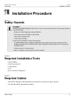
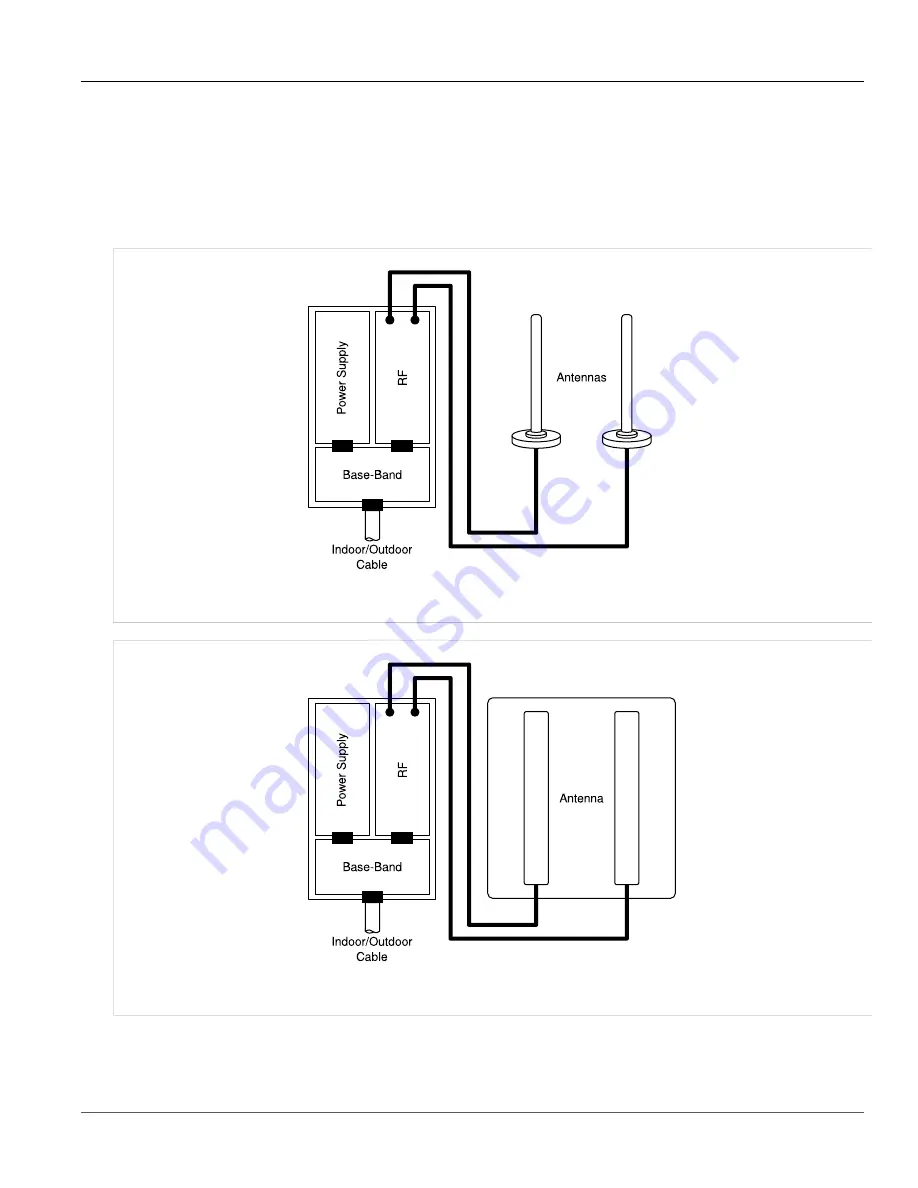
RF board:
single transmit/dual receive module that modulates the analog WiMAX signal input from the
Base-Band modem to the high frequency RF output. Several RF modules exist, each supporting a different
frequency band.
4.
Chassis
5.
Antenna or Antennas:
dual omni or polarization antennas (WiN5100) or integrated dual polarization antenna
(WiN5200) supporting MIMO schemes.
Figure 1: WiN5100 CPE Block Diagram: External Antennas
Figure 2: WiN5200 CPE Block Diagram: Integrated Antenna
Summary of Contents for RUGGEDCOM WiN5100
Page 2: ...RUGGEDCOM WiN5100 WiN5200 User Guide ii ...
Page 8: ...RUGGEDCOM WiN5100 WiN5200 User Guide FCC Statement And Cautions viii ...
Page 26: ...RUGGEDCOM WiN5100 WiN5200 User Guide Chapter 2 Product Description LED Indicators 18 ...
Page 28: ...RUGGEDCOM WiN5100 WiN5200 User Guide Chapter 3 Mounting Wall Mounting 20 ...
Page 106: ...RUGGEDCOM WiN5100 WiN5200 User Guide Appendix A WiN5100 WiN5200 Specifications 98 ...
Page 114: ...RUGGEDCOM WiN5100 WiN5200 User Guide Appendix D RUGGEDCOM CPE Warranty 106 ...