


Chapter 4
Installation Procedure
RUGGEDCOM WiN5100/WiN5200
User Guide
32
Assembling the RJ45 Connector
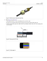
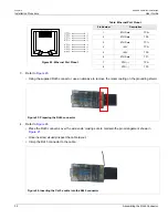
Figure 22: Ethernet Port Pinout
Table: Ethernet Port Pinout
Pin Number
Description
1
ETH Data
TP0+
2
ETH Data
TP0-
3
ETH Data
TP1+
4
+55V
TP2+
5
+55V
TP2-
6
ETH Data
TP1-
7
RTN (-)
TP3+
8
RTN (-)
TP3-
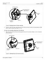
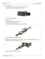
3. Refer to
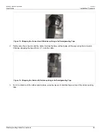
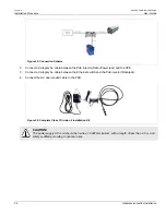
• Using the supplied RJ45 connector, use an abrasive to remove the nickel coating on the grounding shield.
Figure 23: Preparing the RJ45 connector
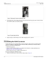
4. Refer to
• Place the RJ45 connector over the wire ends, making sure to maintain the pin arrangement shown in
.
• Once inserted, visually inspect the cable layout.
• Crimp the RJ45 connector to the cable.
Figure 24: Inserting the Cat 5e cable into the RJ45 connector
Summary of Contents for RUGGEDCOM WiN5100
Page 2: ...RUGGEDCOM WiN5100 WiN5200 User Guide ii ...
Page 8: ...RUGGEDCOM WiN5100 WiN5200 User Guide FCC Statement And Cautions viii ...
Page 26: ...RUGGEDCOM WiN5100 WiN5200 User Guide Chapter 2 Product Description LED Indicators 18 ...
Page 28: ...RUGGEDCOM WiN5100 WiN5200 User Guide Chapter 3 Mounting Wall Mounting 20 ...
Page 106: ...RUGGEDCOM WiN5100 WiN5200 User Guide Appendix A WiN5100 WiN5200 Specifications 98 ...
Page 114: ...RUGGEDCOM WiN5100 WiN5200 User Guide Appendix D RUGGEDCOM CPE Warranty 106 ...