


RUGGEDCOM WiN5100/WiN5200
User Guide
Chapter 3
Mounting
Site Survey
19
Mounting
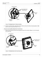
The WiN5100/WiN5200 ODU CPE mounting kit allows for pole or wall mounting.
When choosing the mounting location for the unit, consider the available mounting structures and antenna
clearance.
Section 3.1
Site Survey
Most wireless networks include many CPEs and BSTs installed in various locations in an overlapping radio-
cell pattern. It is important to position each CPE at an optimal location considering the assignment of its radio
channels. Therefore, a site survey becomes an essential first step before physically deploying the WiN5100/
WiN5200 solution.
Installation of the CPEs requires a backhaul connection to interface with the corporate network or Internet. The
backhaul connection can be an Ethernet-wired connection, a wireless–connection, or a third party solution.
The site survey should include a detailed planning of the WiMAX system deployment. The system deployment
plan should include mounting points and the routes for the power and backhaul cables.
Section 3.1.1
Recommended Site Requirements
It is highly recommended that the WiN5100/WiN5200 CPEs be mounted near the edge of the roof of a tall
building. The CPEs should be pointed in the direction of the area to be covered. To provide maximum coverage,
multiple CPEs can be installed on the same rooftop. To prevent interference between the units themselves, it is
important to leave some distance between each unit. When choosing the ideal location, it is also important to take
into consideration the overall area topology.
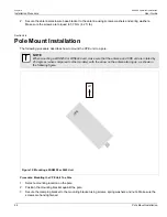
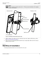
Section 3.1.2
Pole Mounting
You can attach the WiN5100 and WiN5200 to any pipe or pole with a diameter of 1.75" to 10".
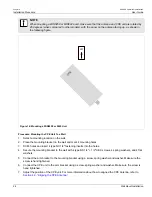
Section 3.1.3
Wall Mounting
You can attach the WiN5100 and WiN5200 to any wall capable of carrying the weight of the unit. An outer wall on
a roof or other high location to avoid interference from other buildings or trees is preferred.
Summary of Contents for RUGGEDCOM WiN5100
Page 2: ...RUGGEDCOM WiN5100 WiN5200 User Guide ii ...
Page 8: ...RUGGEDCOM WiN5100 WiN5200 User Guide FCC Statement And Cautions viii ...
Page 26: ...RUGGEDCOM WiN5100 WiN5200 User Guide Chapter 2 Product Description LED Indicators 18 ...
Page 28: ...RUGGEDCOM WiN5100 WiN5200 User Guide Chapter 3 Mounting Wall Mounting 20 ...
Page 106: ...RUGGEDCOM WiN5100 WiN5200 User Guide Appendix A WiN5100 WiN5200 Specifications 98 ...
Page 114: ...RUGGEDCOM WiN5100 WiN5200 User Guide Appendix D RUGGEDCOM CPE Warranty 106 ...