


Chapter 4
Installation Procedure
RUGGEDCOM WiN5100/WiN5200
User Guide
30
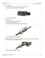
Assembling the RJ45 Connector
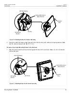
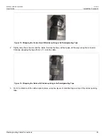
Figure 17: Wrapping the Connector with Electrical Tape
4. Work mastic putty or duct sealing putty between the connector and the body of the radio or antenna. Ensure
the putty fills any gaps not covered by the tape.
Figure 18: Sealing Gaps with Putty
5. Apply two layers of electrical tape over the rubber splicing tape for UV protection.
Section 4.10.2
Assembling the RJ45 Connector
The ODU CPE uses a male, shielded, RJ45 connector to provide the data and Power over Ethernet (PoE)
connection to the device. To assemble the RJ45 connector, follow the instructions in this section. Before
beginning, you will need the following items:
• CPE RJ45 Connector Kit
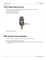
• Category 5e cable of suitable length for your application (for information on cable specifications, see
IDU to ODU Cable Specifications
• Standard cable splicing tools, including a standard crimp tool
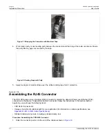
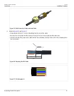
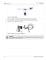
Procedure: Assembling the CPE RJ45 Connector
1. Slide the connector parts on to the end of the cable as shown in
Summary of Contents for RUGGEDCOM WiN5100
Page 2: ...RUGGEDCOM WiN5100 WiN5200 User Guide ii ...
Page 8: ...RUGGEDCOM WiN5100 WiN5200 User Guide FCC Statement And Cautions viii ...
Page 26: ...RUGGEDCOM WiN5100 WiN5200 User Guide Chapter 2 Product Description LED Indicators 18 ...
Page 28: ...RUGGEDCOM WiN5100 WiN5200 User Guide Chapter 3 Mounting Wall Mounting 20 ...
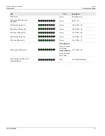
Page 106: ...RUGGEDCOM WiN5100 WiN5200 User Guide Appendix A WiN5100 WiN5200 Specifications 98 ...
Page 114: ...RUGGEDCOM WiN5100 WiN5200 User Guide Appendix D RUGGEDCOM CPE Warranty 106 ...