


Chapter 4
Installation Procedure
RUGGEDCOM WiN5100/WiN5200
User Guide
36
Hazardous Location Installation
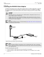
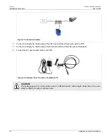
Figure 29: Connection Scheme
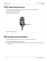
2. Connect a Category 5e cable between the PoE injector (Data+Power jack) and the CPE.
3. Connect a Category 5e cable between the Ethernet switch and the PoE injector (Data jack).
4. Connect the AC open-ended cable to the PSU.
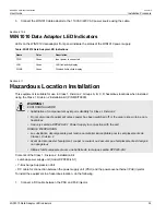
Figure 30: Complete Class 1 Division 2 Installation Kit
CAUTION!
The power supply AC cord should be 3 wires, 18 AWG minimum, with a length of less than 4.5 m, and
safety certified according to national rules.
Summary of Contents for RUGGEDCOM WiN5100
Page 2: ...RUGGEDCOM WiN5100 WiN5200 User Guide ii ...
Page 8: ...RUGGEDCOM WiN5100 WiN5200 User Guide FCC Statement And Cautions viii ...
Page 26: ...RUGGEDCOM WiN5100 WiN5200 User Guide Chapter 2 Product Description LED Indicators 18 ...
Page 28: ...RUGGEDCOM WiN5100 WiN5200 User Guide Chapter 3 Mounting Wall Mounting 20 ...
Page 106: ...RUGGEDCOM WiN5100 WiN5200 User Guide Appendix A WiN5100 WiN5200 Specifications 98 ...
Page 114: ...RUGGEDCOM WiN5100 WiN5200 User Guide Appendix D RUGGEDCOM CPE Warranty 106 ...