Chapter
2
Reference Manual
IVC-2D
20
©
SICK AG • Advanced Industrial Sensors • www.sick.com • All rights reserved
Getting Started
20.
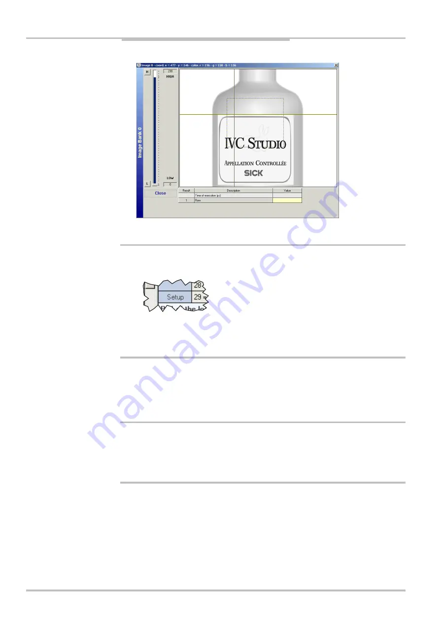
Click on the
H
(Gray High) or
L
(Gray Low) button, and adjust the upper or lower gray
value with the slider, so that the edge of the label is clearly visible within the ROI.
Certain tools have interactive setup windows in which you can set all parameters. These
tools have a
Setup
field in the bottom left corner of the program step in the program list. To
open the setup window, double-click the
Setup
field.
When all parameters have been set for the Find Column Edge step, we can duplicate the
step and use the copy to find the edge on the right side – just change the line to search
along.
21.
Select the
Find column edge
and choose
Edit
Æ
Copy
from the main menu.
22.
Choose
Edit
Æ
Paste
.
23.
Set the line to scan along in the new
Find column edge
step by moving it in the preview
window.
24.
Change the description of the program step to “Find right edge”.
2.4.2
Using Tables and Results from Other Steps
We will need the x coordinates for the lines when we calculate the angle of the top edge of
the label. Therefore it is useful to store these values in the table instead of having to set
them manually for each step in which they are used:
25.
Select the “Find left edge” step, and copy the value of the parameter
02=Column
.
This value is the x coordinate for the left point of the label.
26.
Paste the value into an empty row in the
Value on Device
column in the table.
The row is now highlighted in the table, indicating that the value on the device differs
from the value in the database.
You may also enter a description for the row, describing what the value is used for.


