background image

8  Setting the Analytical Parameters and File Management
8.2 File Management

96

GC-2014

8.2.3

Copying a file

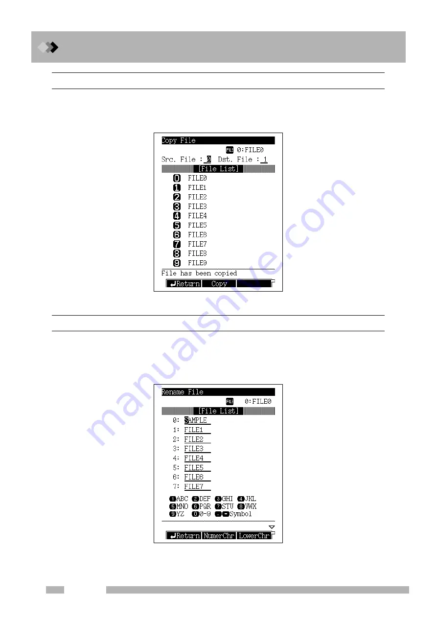
Select [Copy] (PF menu) on the file list screen to display the file copy screen shown in Fig. 8.2.2.
Enter the source file number (Src. File) and the destination File number (Dst. File), then press
[Copy] (PF menu). The name and contents of the source file are copied to the destination file.

8.2.4

Renaming a file

Select [Rename] (PF menu) on the file list screen to display the file rename screen shown in
Fig. 8.2.3. Move the cursor using the [

] and [

] keys to select the file to be renamed.

Enter the new file name using the numeric keys and the [

] and [

] keys. Refer to  

“6.3.5

Changing item names”

 for more information..

Fig. 8.2.2


Copying File

Fig. 8.2.3


Renaming a file

Summary of Contents for GC-2014

Page 1: ...221 40609A GC 2014 Gas Chromatograph INSTRUCTION MANUAL Read the instruction manual thoroughly before you use the product Keep this instruction manual for future reference ...

Page 2: ...bject to change without notice and does not represent a commitment on the part of the vendor Any errors or omissions which may have occurred in this publication despite the utmost care taken in its production will be corrected as soon as possible but not necessarily immediately upon detection Note that Shimadzu does not have any obligation concerning the effects resulting from the appli cation of ...

Page 3: ...them Safety precautions are included in the operation manual Please read them before using the instrument Label conventions for this manual are provided below WARNING Indicates a potentially hazardous situation which if not avoided could result in serious injury or possibly death CAUTION Indicates a potentially hazardous situation which if not avoided may result in minor to moderate injury or equi...

Page 4: ...This page is intentionally left blank ...

Page 5: ...umns and Setting Analytical Flow Lines 3 1 Installation Location for Packed Columns 31 3 2 Dual Column Packed FID Analysis 33 3 3 Single Column Packed FID Analysis 36 3 4 Packed TCD Analysis 39 3 5 Packed Analysis Using the Single DET 42 4 Installing Capillary Columns and Setting Analytical Flow Lines 4 1 Installation Location for Capillary Columns 47 4 2 Capillary Analysis Using the Dual FID When...

Page 6: ...1 Screen Description 79 7 1 2 Parameter 80 7 1 3 PF menu 81 7 2 Specifying Clean Up Parameters 82 7 2 1 Screen Description 82 7 2 2 Parameter list 83 7 2 3 PF menu 85 7 3 Specifying Start Procedures 86 7 3 1 Screen description 86 7 3 2 Parameter list 87 7 3 3 Example starting the system with carrier gas flow 87 7 4 Specifying the Stop Procedures 88 7 4 1 Screen 88 7 4 2 Parameter list 88 7 4 3 Sys...

Page 7: ...ing an Injecting and Starting an Analysis 109 10 1 1 Verifying the gas chromatograph status 109 10 1 2 Making manual injection 110 10 1 3 Starting the analysis 111 10 2 Terminating the Analysis 112 10 2 1 Terminating the analysis 112 10 2 2 External devices 112 11 Creating an Oven Temperature Program 11 1 COL Key Main Screen 113 11 1 1 Screen description 113 11 1 2 Parameter list 114 11 1 3 PF men...

Page 8: ...Gas manual flow controller 157 13 1 4 Setting the detector gas flows APC 159 13 1 5 Igniting and Extinguishing the FID 161 13 2 Thermal Conductivity Detector TCD 164 13 2 1 Principle of TCD operation 164 13 2 2 Setting the detector 165 13 2 3 TCD Zero Point Adjustment 169 13 3 Filter Signal Time Constant 170 13 4 Background Compensation 171 14 Diagnosis 14 1 Standard Diagnosis 173 14 1 1 Screen de...

Page 9: ...ameter list 198 15 1 6 PF menu 199 15 1 7 Other AOC parameters 199 15 1 8 Other AOC Parameter 200 15 1 9 PF menu 201 15 1 10 Auto sampler carousel and other optional parameters 202 15 1 11 Parameter list 202 15 2 Setting AUX Temperature 203 15 2 1 Screen description 203 15 2 2 Parameter list 203 15 2 3 PF menu 203 15 2 4 On Off setting 204 15 2 5 On Off parameter list 204 15 3 Setting the AUX APC ...

Page 10: ...3 5 Time Program parameters 227 16 3 6 Editing a time program 228 16 3 7 Time program setup example 229 16 4 Pre Run Program 231 16 4 1 Screen description 231 16 4 2 PF menu 231 16 4 3 Creating a new Pre Run program 232 16 4 4 Editing a Pre Run program 232 16 4 5 After Pre Run program is finished 232 16 4 6 Pre Run Program set up example 233 16 5 Direct Operation 234 16 5 1 Screen description 234 ...

Page 11: ...escription 269 16 10 2 Parameter list 269 17 Printing 17 1 Printing 271 17 1 1 Connection to Chromatopac 271 17 1 2 Parameters to be printed 271 17 2 AOC commands 275 17 3 Program Parameters 277 17 4 Event No 279 18 Error Messages 18 1 Error Messages 283 18 1 1 System errors 283 18 1 2 Temperature control errors 286 18 1 3 Pressure flow rate errors 289 18 1 4 Communication errors 293 18 1 5 Detect...

Page 12: ...Contents viii GC 2014 This page is intentionally left blank ...

Page 13: ...ge 5 to 90 Avoid use under conditions where con densation forms 2 Installation location Install the unit on a firm stable and flat base The GC 2014ATF model weighs approximately 50 kg 3 Corrosive gas and dust Avoid exposure to corrosive gas and excessive dust to prolong the service life and maintain optimal unit performance 4 Electro magnetic fields and power supply noise This unit should not be u...

Page 14: ... a clearance of 50 mm or more on the left side 4 Allow a clearance of 100 mm or more on the right side in order to have a space to open close the oven door 5 Reserve extra space for maintenance and inspection behind the unit When the optional exhaust air duct P N 221 70675 91 is used rear space of 200 mm or more is required WARNING Hot air Hot air is exhausted from the vent Do not place flammable ...

Page 15: ...wo people must carry the GC one on the left and one on the right with their hands between the rubber legs on the left and right side of the unit 3 Do not hold the oven door when carrying the GC because it may break the door 4 Do not put your hands on the rubber legs or along the front rear direction of the unit because your fingers may get trapped under the unit when placing it on a table ...

Page 16: ...15 V model 2 750 VA 230 V model Optional temperature control block INJ etc 150 VA pc Maximum power is 2600 VA 115 V model 3400 VA 230 V model Performance of the unit may be affected if the power supply voltage fluctuates or the capacity is insufficient Q Connecting the power cable The power cable of the 230 V model uses a plug Fig 1 2 1 Plug WARNING HIGH VOLTAGE 1 Before connecting the power cable...

Page 17: ...d to NEUTRAL of AC line Green Grounding GROUND Fig 1 2 2 Power cable Q Symbol conventions AC Off Open On Close Q Heating energy generation The following graph shows the heating values generated by the unit Fig 1 2 3 Black White Green Power cable ON status Power switch OFF status 0 0 0 5 1 1 5 2 2 5 3 3 5 100 200 300 400 Temperature Heat generation 10 6 J hour ...

Page 18: ...igured analytical flow lines to prevent the heater from turning ON 3 Set the column oven temperature to 300 C and start the GC 4 Keep the column temperature at 300 C for 2 hours or more Fuse No Rated current voltage Type Classification depending on IEC127 115 V model 230 V model F1 F2 15 A 250 V 10 A 250 V T F3 F4 5 A 250 V 3 15 A 250 V T F5 F6 5 A 250 V 5 A 250 V T CAUTION GC 2010 may get wet fro...

Page 19: ...en which is more reasonable than helium can also be used the optimum separation conditions may not be reached Makeup gas types Capillary FID Both helium and nitrogen can be used Nitrogen has a slightly higher sensitivity Capillary TCD The same gas is used as makeup gas and reference gas for capillary TCD Select a type of gas by the same method to select carrier gas 2 Gas purity Helium carrier gas ...

Page 20: ... 500 kPa Makeup gas 300 980 kPa Hydrogen 300 500 kPa Air 300 500 kPa The relationship of kPa and bar is as follows 100 kPa 1 bar Convert units between kPa and kgf cm2 as follows 1 kPa 1 02 10 2 kgf cm2 1 kgf cm2 98 1 kPa Convert the units between kPa and psi as follows 1 kPa 1 45 10 1 psi 1 psi 6 89 kPa NOTE ...

Page 21: ... When using high pressure gases pay strict attention to ventilation and perform daily leak checks In particular when using flammable gases such as hydrogen never smoke or allow open flame within 5 m of the equipment Fire extinguishers must be present Secure gas cylinders firmly with cylinder clamps so they cannot fall over Use oil free pres sure valves only Never use tubing which has contacted oil...

Page 22: ...ent an explosion due to a hydrogen gas leak the room in which the unit is used should be well ventilated Prohibit the use of open flame in this room 5 Close the main valve of the hydrogen cylinder immediately after completing the analyses Then turn OFF the unit and perform normal shut down procedures WARNING HYDROGEN GAS HANDLING PRECAUTIONS The accumulation of hydrogen gas inside the column oven ...

Page 23: ...eiling Pay strict attention to ventilation so that leaking hydrogen is vented out of the room and cannot accumulate WARNING Hydrogen carrier gas precautions If much hydrogen gas is released into the poorly ventilated room it may cause the explosion 1 In order to prevent hydrogen gas accumulate in the room attach tubes to split vent purge vent TCD vent and ECD vent Discharge the gas to open air or ...

Page 24: ...irectly Type G connectors which are used in high temperature areas are connected by tightening three to five aluminum gaskets between the fittings Fig 1 3 1 Joining Type M fittings Fig 1 3 2 Joining Type G fittings Tightening the tubing connections Tools 2 wrenches 10 12 standard accessory Use the 12 mm wrench for Type M connections and the 10 mm wrench for type G connections Fig 1 3 3 Tightening ...

Page 25: ...The use of a gas filter is highly recommended Contaminated tubing or poor quality gases can interfere with baseline stability Option Gas filter P N 221 05619 01 This absorbs organic compounds and moisture in the supply gas improving its purity The filter can be regenerated by baking in the GC oven at 250 C with 30 mL min carrier gas purging the filter Capacity Approx 200 mL Absorbent Molecular sie...

Page 26: ...s follows Carrier gas CARRIER L and R mean the left and right side of dual INJ Makeup gas MAKE UP Hydrogen HYDROGEN Air AIR Fig 1 3 6 Plumbing Example of the GC 2014ATF SPL model Flow controller for the dual FID Right Left AFC for SPL AFC for the dual INJ Supply the carrier gas for the left inlet of the dual INJ to CARRIER L and the carrier gas for the right inlet of the dual INJ to CARRIER R ...

Page 27: ...ck for leaks with leak detecting fluid option or soapy water on all connections Bubbles can be observed if a leak exists 4 If a leak is detected Further tighten the connection or retighten it Replace the seal material 5 Wipe off the leak detecting fluid or soapy water using a wet cloth Electronic leak detectors can also be used for hydrogen and helium leaks Option Snoop Gas leak detecting fluid P ...

Page 28: ...1 Installation 1 3 Gas Supply Plumbing 16 GC 2014 This page is intentionally left blank ...

Page 29: ...nefits during operation 1 Conditions of analytical parameters for each line can be set and monitored For example when the SET key of the gas chromatograph is pressed temperatures of columns injection ports and detectors as well as carrier gas flow rate can be set and monitored on a single screen 2 A protective mechanism operates to foster more stable operation conditions For example when a carrier...

Page 30: ...wing page for setting procedures Connections of the flow controller s and injection port s and connections of detector cell s and detector amplifier s are specified by a serviceperson at shipment or installation They do not need to be specified for regular analysis Fig 2 1 2 shows a representative example of the line configuration for packed column FID analysis using the GC 2014 In this example th...

Page 31: ...column s temperature rises in this condition the column may be damaged To keep feeding gas to units or maintain their temperature even though they will not be used for analysis for a while specify the units as part of a line 2 Remove the units not in use from a line Examples If a detector without a column stays on a line it may damage TCD filament or cause an error such as FID ignition error If th...

Page 32: ...atopac signal cable to the connector ANALOG OUT1 or 2 on the back of the GC Fig 2 2 1 Using this cable analog signals can be outputted and the Chromatopac can be started when the GC starts Refer to 16 6 9 Setting the link device code A N A L O G O U T 2 A N A L O G O U T 1 A O C I N J E C I O R 1 I N J E C I O R 2 S A M P L E R E V E N T O P T I O N 1 2 3 4 5 6 R S 2 3 2 C R S 2 3 2 C OP1 LINKSTAR...

Page 33: ...does not appear 2 Set analog signal output 1 Press the DET key 2 The outlined part is a parameter for analog signal output for all detectors Set the parameter following the description below For Background signal save compensation and Detector signal subtraction refer to Chapter 13 Detector DET Signal Output Port Specify a connector number to output analog signals ANALOG OUT 1 Ch1 ANALOG OUT 2 Ch2...

Page 34: ...matopac Perform calibration in the following cases When the GC and Chromatopac are connected for the first time during installation When the GC or Chromatopac is changed with other instrument When a connection channel number is changed by switching a connector on the GC side When a two channel board is installed on the Chromatopac and a connection channel number is changed by switching a connector...

Page 35: ...n to the connector on the back of the GC Fig 2 3 1 To connect one PC with more than one GCs separate RS 232C cables are necessary and an expanded COM port needs to be attached to the PC AOC built in power source has the same connector Connect the cables correctly NOTE A N A L O G O U T 2 A N A L O G O U T 1 A O C I N J E C I O R 1 I N J E C I O R 2 S A M P L E R E V E N T O P T I O N 1 2 3 4 5 6 R...

Page 36: ...2014 Setting transmission parameters 1 Select 6 GC CONFIGURATION on the FUNC key screen and then select 3 TRANSMISSION PARAMETER 2 Set transmission parameters Protocol LEVEL3 Baud rate bps 115200 3 Press the PF2 key Apply Turning ON the power of the GC is not necessary NOTE ...

Page 37: ...ting RS 232C cable Connect an optional RS 232C cable to the connector on the back of the GC Fig 2 4 1 AOC built in power source has the same connector Connect the cables correctly NOTE A N A L O G O U T 2 A N A L O G O U T 1 A O C I N J E C I O R 1 I N J E C I O R 2 S A M P L E R E V E N T O P T I O N 1 2 3 4 5 6 R S 2 3 2 C R S 2 3 2 C OP1 LINKSTART OUT READY IN START IN READY OUT AOC POWER SUPPL...

Page 38: ... T TRS 2 Press the key until the STD2 Port RS 232C Setup screen appears 3 Set transmission parameters MODE 12917 Protocol LEVEL2 Stop bit 1 bit Parity EVEN No 8 logical port number BPS 9600 baud rate 4 After completing setting press the EXIT key and then press the Y key to save the settings 5 After changing transmission parameters reboot the C R8A to enable the new settings Procedures to start dig...

Page 39: ... or auto sampler There are two identical RS 232C connectors Make sure to make the correct connections NOTE A N A L O G O U T 2 A N A L O G O U T 1 A O C I N J E C I O R 1 I N J E C I O R 2 S A M P L E R E V E N T O P T I O N 1 2 3 4 5 6 R S 2 3 2 C R S 2 3 2 C OP1 LINKSTART OUT READY IN START IN READY OUT AOC POWER SUPPLY START OUT Back of the GC AOC built in power source SMAPLER auto sampler INJE...

Page 40: ...rce will be automatically linked 2 Set AOC parameters 1 Press the OPTION key If other option screens appear press the OPTION key repeatedly until the AOC Parameter screen appears 2 Set AOC parameters Parameters will be transmitted to the AOC as soon as they are set For detailed information about setting AOC parameters refer to 15 1 Auto Injector Parameters or AOC 20 user s manual If the AOC Parame...

Page 41: ...hey are connected by EVENT91 and disconnected by EVENT 91 If it is connected to COM and NC they will be connected by EVENT 91 and disconnected by EVENT91 1 3 1 2 A N A L O G O U T 2 A N A L O G O U T 1 A O C I N J E C I O R 1 I N J E C I O R 2 S A M P L E R E V E N T O P T I O N 1 2 3 4 5 6 R S 2 3 2 C R S 2 3 2 C OP1 LINKSTART OUT READY IN START IN READY OUT AOC POWER SUPPLY START OUT Back of the...

Page 42: ...2 Before Use 2 6 Connecting the Relay Terminals 30 GC 2014 This page is intentionally left blank ...

Page 43: ... 1 Table 3 1 1 Installation location for injection ports detectors for packed columns Installation location numbers indicate the positions of column connecting joints Name Possible installation location Injection ports Dual INJ 1 2 2 3 3 4 Single INJ 1 4 Detectors Dual FID 6 7 TCD 9 10 Single DET 5 6 7 8 Fig 3 1 1 Fig 3 1 1 Installation location for injection ports detectors for packed columns lay...

Page 44: ... Check which units the joints found on the column oven correspond to Fig 3 1 2 shows the layout for the GC 2014ATF SPL model Left and right sides viewed from the front of the unit are indicated as L left and R right respectively Fig 3 1 2 Column connecting joints GC 2014ATF SPL model SPL Dual INJ Dual FID 4 L R TCD 4 ...

Page 45: ...s 1 Same type of columns are connected to the left and right sides in order to background compensate the increase of the baseline during programmed temperature analysis 2 Different types of columns are connected to the left and right sides in order to obtain a different chromatogram when a sample is injected to the left L side and right R side of the dual INJ Do not cross the columns L R It hinder...

Page 46: ...ribed below For procedures to install columns and input analytical conditions refer to the operation manual 1 Set a line 1 Press the SET key and then press the PF2 key Line Config 2 Set the dual INJ DINJ and dual FID DFID on a same line LINE1 is specified in the example below Lines 1 through 4 can be selected 2 Set the dual AFC 1 Press the FLOW key 2 Set Control mode to Dual ...

Page 47: ...Analysis 35 GC 2014 3 Set the dual FID 1 Press the DET key 2 Set Control mode to Dual 3 Set Signal polarity as described below The FID L FID R signal is outputted When a sample is injected into the dual INJ L The FID R FID L signal is outputted When a sample is injected into the dual INJ R ...

Page 48: ...ckground compensation is unnecessary because the baseline level does not increase so much even during programmed temperature analysis 1 When single column configuration is set unspecified flow controller does not supply gases Make sure to remove unspecified column to prevent deterioration 2 Make sure to stop the FID detector gas supply hydrogen and air on unspecified side Turn the control of the f...

Page 49: ...itions refer to the operation manual 1 Set a line 1 Press the SET key and then press the PF2 key Line Config 2 Set the dual INJ DINJ and dual FID DFID on a same line LINE1 is specified in the example below Lines 1 through 4 can be selected 2 Set the dual AFC 1 Press the FLOW key 2 Set Control mode as described below Set to Single L when the column is connected to the left L side of the dual INJ an...

Page 50: ...s 3 3 Single Column Packed FID Analysis 38 GC 2014 3 Set the dual FID 1 Press the DET key 2 Set Control mode as described below Set to Single L when the column is connected to the left L side of the dual FID and Single R when it is connected to the right R side ...

Page 51: ...mple is injected to the L and R of the dual INJ 1 Do not cross the columns L R It hinders correct analysis 2 If left and right columns are extremely different e g liquid quantity flow rate zero point may not be achieved by turning the control on the right side of the GC unit In this case adjust the column flow rate on the side that a sample is not analyzed reference side Fig 3 4 1 Dual column conf...

Page 52: ...ed below For procedures to install columns and input analytical conditions refer to the operation manual 1 Set a line 1 Press the SET key and then press the PF2 key Line Config 2 Set the dual INJ DINJ and TCD DTCD on a same line LINE1 is specified in the example below Lines 1 through 4 can be selected 2 Set the dual AFC 1 Press the FLOW key 2 Set Control mode to Dual ...

Page 53: ...NJ R TCD signals do not necessarily have a plus peak because they are determined by relationship of heat conduction between a substance to be analyzed and carrier gas However the data processing unit normally calculates the area of a plus peak When a minus peak is detected signal polarity needs to be inverted into a plus peak In this case inject a sample into the opposite inlet of the one instruct...

Page 54: ...When a SUS column is used the dual INJ does not need to be moved 2 If the single packed INJ is installed in front of the single DET analysis can be performed without moving the dual INJ For detailed descriptions refer to instruction manual of the single packed INJ Fig 3 5 1 Single DET configuration CAUTION Dual INJ is set on the single mode so carrier gas is not fed to the unspecified port L on th...

Page 55: ...prove workability 5 Unfasten the three screws that fasten the dual INJ Fig 3 5 2 a and pull the dual INJ upward Sems screws with a flat washer are used Be careful not to drop flat washers 6 Take out the heat insulator laid on the bottom of the dual INJ using tweezers or other similar tools WARNING Carry out the procedures after the injection port becomes 40 C or less to prevent burns CAUTION Some ...

Page 56: ...proximately 3 cm thick Cut the sheet metal on the bottom of the heat insulator as well 8 Move the cut heat insulator to the left 9 Insert the dual INJ on top of the heat insulator that has been taken out in step 6 and fasten it with three screws Refer to Fig 3 5 2 c 10 Connect the wiring that has been removed in step 4 to the dual INJ as it was originally Fig 3 5 2 b Fig 3 5 2 c 50mm Screws sems s...

Page 57: ...er to the operation manual 1 Set a line 1 Press the SET key and then press the PF2 key Line Config 2 Set the dual INJ DINJ and single DET PECD in the screen below on a same line LINE1 is specified in the example below Lines 1 through 4 can be selected 2 Set the dual AFC 1 Press the FLOW key 2 Set Control mode as described below Set to Single L when the column is connected to the left L side of the...

Page 58: ...3 Installing Packed Columns and Setting Analytical Flow Lines 3 5 Packed Analysis Using the Single DET 46 GC 2014 This page is intentionally left blank ...

Page 59: ...used for packed columns are included Table 4 1 Installation location for injection ports detectors for capillary columns Installation location numbers indicate the positions of column connecting joints Name Possible installation location Injection ports SPL 1 4 WBI 1 4 Dual INJ 1 2 2 3 3 4 Single INJ 1 4 Detectors Dual FID 6 7 Single DET 5 6 7 8 FTD 2014c 11 12 TCD 9 10 Fig 4 1 1 Installation loca...

Page 60: ...n oven correspond to Fig 4 1 2 a and b show the layout for the GC 2014ATF SPL model and GC 2014AFsc model Left and right sides viewed from the front of the unit are indicated as L left and R right respectively Fig 4 1 2 a Column connecting joints GC 2014ATF SPL model Fig 4 1 2 b Column connecting joints GC 2014AFSC model SPL Dual INJ Dual FID 4 4 Dual TCD 4 52 Single FID ...

Page 61: ...dapter with purge P N 221 34012 91 to the joint of the dual FID Connect the purge piping of the adapter to the dual INJ so that makeup gas is supplied from the dual AFC through the dual INJ The dual AFC is off the line and operates as an independent mass flow controller Although an adapter and column are connected to the right R sides of the dual INJ and dual FID in the figure below they can be co...

Page 62: ... and input analytical conditions refer to the operation manual 1 Change the dual AFC configuration 1 Select 6 GC CONFIGURATION on the FUNC key screen and then select 9 Other configuration 2 Specify AMC LR at DAFC unit 2 Set a line 1 Press the SET key and then press the PF2 key Line Config 2 Set the SPL and dual FID DFID on a same line LINE1 is specified in the example below Lines 1 through 4 can b...

Page 63: ...ey 2 Set AMC L when the detector adopter is connected to the left L side of the dual INJ and set AMC R when it is connected to the right R side Start control and set the makeup gas flow rate and gas type 4 Set the dual FID 1 Press the DET key 2 Set Control mode as described below Set to Single L when the column is connected to the left L side of the dual FID and Single R when it is connected to th...

Page 64: ... supply makeup gas the optional makeup gas flow controller P N 221 70877 91 1 flow path 221 70877 92 2 flow paths are used Prior to installing a column install the detector adapter P N 221 33193 91 to the detector s joint Although an adapter and column are connected to the right R side of the dual FID in the figure below they can be connected to either side L R Fig 4 3 1 Dual FID flow controller C...

Page 65: ...and columns and input analytical conditions refer to the operation manual 1 Set a line 1 Press the SET key and then press the PF2 key Line Config 2 Set the SPL and dual FID DFID on a same line LINE1 is specified in the example below Lines 1 through 4 can be selected 2 Set the dual FID 1 Press the DET key 2 Set Control mode as described below Set to Single L when the column is connected to the left...

Page 66: ...ss flow controller Reference gas is supplied from the dual AFC when the dual INJ and TCD are connected with a MF MF joint The figure above shows an example where makeup gas and reference gas are connected to the left L and right R sides of the dual INJ respectively and a column and reference gas piping are connected to the left L and right R sides of the TCD respectively They can be connected to e...

Page 67: ...er to the operation manual 1 Change the dual AFC configuration 1 Select 6 GC CONFIGURATION on the FUNC key screen and then select 9 Other configuration 2 Specify AMC LR at DAFC unit 2 Set a line 1 Press the SET key and then press the PF2 key Line Config 2 Set the SPL and dual TCD DTCD on a same line LINE1 is specified in the example below Lines 1 through 4 can be selected If the dual AFC is specif...

Page 68: ...art controlling both AMC L and AMC R and set the flow rates and gas types according to the connection of detector adopter and reference gas piping 4 Set the TCD 1 Press the DET key 2 Set Signal polarity as described below The TCD L TCD R signal is outputted When a column is connected to TCD L and a sample that a plus peak is detected is injected The TCD R TCD L signal is outputted When a column is...

Page 69: ...hip of heat conduction between a substance to be analyzed and carrier gas However the data processing unit normally calculates the area of a plus peak When a minus peak is detected signal polarity needs to be inverted into a plus peak Signal polarity can be changed using the time program during analysis For detailed descriptions about setting the time program refer to 16 3 Time Program NOTE ...

Page 70: ...keup gas is used as described below Install the detector adapter to the detector joint then install a column Detector adapter comes with all single DET units listed above A makeup gas flow controller comes with them Makeup gas is unnecessary Fig 4 5 1 Single DET In case of FID Single FID ECD and capillary FTD FPD Column Detector adapter Single DET SPL AFC Hydrogen Makeup gas Flow controller ...

Page 71: ... flow lines is described below For procedures to install columns and input analytical conditions refer to the operation manual 1 Set a line 1 Press the SET key and then press the PF2 key Line Config 2 Set the SPL and single DET SFID in the screen below on a same line LINE1 is specified in the example below Lines 1 through 4 can be selected ...

Page 72: ...4 Installing Capillary Columns and Setting Analytical Flow Lines 4 5 Single DET 60 GC 2014 This page is intentionally left blank ...

Page 73: ...mperature of the Set the temperatures on the INJ and DET key screens If the detector detector and the injection port is set to Off turn it On When the APC is used set hydrogen air makeup gas etc from DET Gas PF menu Set the COL temperature and From the screen of the COL key set the column initial temperature the temperature program and the temperature program Temperature settings must be within th...

Page 74: ...if necessary Inject the sample Aspirate the sample in the syringe inject it into the GC injection port and press START to analyze it WARNING Wear protective goggles when using a syringe to inject samples The syringe plunger could be expelled due to injection port back pressure Sample could get into the eyes By holding and supporting the plunger from the side with your middle finger you can smoothl...

Page 75: ...he injected sample to enter the column This method is useful for samples of high consentration or about which nothing is known Try to perform a split injection method first Set the split ratio to approximately 1 50 If the target peak is too large increase the split ratio If the target peak is too small or cannot be detected decrease the split ratio Select a proper split ratio in this way If the pe...

Page 76: ...and reset the counter limit Set the limit to perform maintenance on a regular basis The septum glass insert replacement cycle varies depending on the analytical conditions and samples If the glass insert is easily contaminated when analyzing non volatile com punds for example set a low counter limit On the other hand when analyzing cleaner sam ples the limit can be increased Q Starting up the GC T...

Page 77: ...t Stop GC PF menu When shutting down the GC the heated zones are cooled and then the carrier gas flow is turned off To accomplish these in the correct sequence automatically use a stop time this stops temperature control at the set time and flow off time turns off carrier gas flow at the set time Do not turn off the GC without first selecting Stop GC PF menu Q Obtaining reproducible analysis resul...

Page 78: ...5 Analysis 5 2 Notes for Analysis 66 GC 2014 This page is intentionally left blank ...

Page 79: ...mmable functions displayed at the bottom of the screen Toggle key Toggles among PF items displayed Toggle key Cursor keys Sets On Off of backlight and adjustment of contrast Cursor keys Moves the cursor up down left and right respectively Numeric keys Inputs numeric values ENTER key Validates input or selection CE key Clears a numeric input or error HELP key Explains currently displayed items UNIT...

Page 80: ...ell as chromatograms SET key Accesses commonly used items such as temperature pressure and flow rate for each component on one screen Manages the analytical condition file like the SYSTEM key FUNC key Accesses less frequently used items COL key Sets the oven temperature program FLOW key Sets the carrier gas flow rate parameters such as pressure flow rate and split ratio INJ key Sets the temperatur...

Page 81: ...creen Return PF menu is displayed in PF1 Q Actual and set values Actual current values are highlighted while set values are underlined The actual value blinks when it is NOT READY the actual value has not reached the set value When the values are equal READY status the actual value stops blinking When the DINJ is used When the SPL is used Fig 6 1 1 When the DINJ is used When the SPL is used Fig 6 ...

Page 82: ... Diagnosis baking or flow controller calibration is being executed Red On An error has occurred in system Color Status Meaning Off Temperature control is not performed Green On All temperature controlled zones are ready Blinking Temperature program is running Yellow On One of the temperature controlled zones is not ready Blinking Temperature program is finished and system is being cooled Red On An...

Page 83: ...on When the keypad is not in use turning the backlit LCD display off is recommended to pro long the life of the display The display turns off automatically with the backlit display saver See 16 6 11 Other Settings When the display turns itself off turn it back on by pressing any key To adjust the contrast the contrast stand in front of the screen and press the Toggle or keys Fig 6 2 1 NOTE PF1 PF2...

Page 84: ...e PF menu includes direct operations some PF menu items do not have secondary screens Q PF menu item selection Select a desired PF menu item by pressing the PF keys PF1 PF2 and PF3 underneath the screen which correspond to PF menu items Fig 6 3 1 If the PF menu continues over two or more pages press the Toggle key to display the desired PF menu then press the PF key Example 1st page of PF menu Pre...

Page 85: ...cursor The and keys may perform a different function Q Moving the cursor using the and keys Example Main screen of the COL key Q Moving the cursor using only the and keys Example Main screen of the FLOW key Fig 6 3 2 Fig 6 3 3 Move the cursor using the and keys Move the cursor to each parameter using the and keys Items marked with and use the and keys to change the selection In this case the selec...

Page 86: ... 6 3 4 Changing a selection Parameters marked with and are changed by making another selection Change the selection using the following procedure 1 Move the cursor to the item 2 Select a desired choice by pressing the and key 3 Press the ENTER key to validate the selection The selection change becomes valid when the ENTER key is pressed If you move the cursor or display another screen before press...

Page 87: ... the cursor to an item to be changed using the and keys 2 Move the cursor to a character to be changed using the and keys 3 Input a character as described in the following section on entering characters The character input procedure described below 4 Press the ENTER key to validate the input 5 Repeat steps 2 to 4 to enter a name 6 Press the CE key to delete one character at the cursor s current po...

Page 88: ...NumerChr PF menu to select the numeric mode Alphabetic mode upper case lower case Numeric mode Press the 0 to 9 keys to input numbers 0 to 9 Press the and keys to toggle the symbols Key Toggled characters 1 A a B b C c A a 2 D d E e F f F f 3 G g H h I i G g 4 J j K k L l J j 5 M m N n O o M m 6 P p Q q R r P p 7 S s T t U u S s 8 V v W w X x V v 9 Y y Z z Y y 0 0 1 2 3 4 5 6 7 8 9 0 blank blank b...

Page 89: ...ig 6 4 1 appears when the HELP key is pressed on the DIAG key screen Items which may be difficult to understand are linked to further descriptions Set the cursor on one of these underlined items and press Display PF menu to access to the linked descriptions Fig 6 4 2 shows the pop up screen linked to the word log on the screen shown in Fig 6 4 1 6 4 2 PF menu Display Back Fig 6 4 1 Help screen Fig...

Page 90: ...6 Basic Key Operation 6 4 Getting Help 78 GC 2014 This page is intentionally left blank ...

Page 91: ...press Start GC PF menu The GC starts then enters standby mode according to the main screen setting However if the GC is in system ON mode pressing the SYSTEM key will access the screen shown in Fig 7 1 2 Here set up parameters relating to turning off the GC such as stop time flow off time sleep time etc Once the parameters have been specified press Stop GC PF menu to begin the GC stop operations I...

Page 92: ...to run the clean up program after the GC enters Ready status If the maximum temperature of the clean up oven temperature program is too close to maximum temperature of the column select Analysis Para to perform clean up using a regular analysis program STOP TIME Range 0 0 6000 0 min Default 0 0 min Sets the period of time after Stop GC PF menu is pressed or after a program finishes if the program ...

Page 93: ...ad edit copy initialize and rename 8 2 Clean Up Sets clean up parameters In system ON status select direct operation PF menu to run the clean up 7 2 Start Seq Sets the parameters for the next GC start up Start time detector and clean up parameters on this sub screen are immediately reflected on the SYSTEM key main screen 7 3 Stop Seq Sets the stop procedures This item is not displayed in system ON...

Page 94: ...parameter setup screen shown in Fig 7 2 1 The parameters set for the clean up program are set by including Clean Up Para as part of the GC start procedure Clean up should be performed to eliminate contamination before analysis Reform the clean up when the gas chromatograph has not been used for a while or if a new column has been installed a DINJ b SPL Fig 7 2 1 Setting the clean up parameters ...

Page 95: ...Refer to Fig 12 2 15 Default 3 0 ml min Sets the septum purge flow rate for the clean up method The septum purge removes contamination in the injection port near the septum If the split ratio is set to 1 0 the total flow rate remains fixed regardless of to the oven temperature SPLIT RATIO Range 1 0 0 0 9999 9 Default 1 0 Sets the split ratio for the clean up method Set the split ratio to 1 0 for t...

Page 96: ...m Do not exceed the maximum column temperature CLEAN UP TIME Range 0 00 9999 99 min Default 0 00 min Sets the final temperature hold time for the clean up program Q Clean up column Inlet pressure program when the AFC control mode is pressure The clean up pressure program consits of a single program ramp CLEAN UP RATE Range END 400 00 400 00 kPa Default END Sets the rate of column inlet pressure fo...

Page 97: ...d when the control mode is pressure on the FLOW key screen of the AFC 12 5 5 Flow Prog Sets the flow rate for the clean up program Sets the column flow rate program for the DAFC and the total flow rate program for the AFC Display is possible for the DAFC and when the control mode is set at flow rate on the FLOW key screen of the AFC 12 5 6 Run Displayed only while GC is in system ON status Immedia...

Page 98: ...urned on or whether the system does not start until Start GC PF menu is pressed Manual Start Alternatively only carrier gas flow is turned on the next time the power is turned on To start the system select Start GC PF menu as for a manual start This is known as a semi auto start Finally an analysis file can be set to begin the next time the power is turned on or the GC is restarted Any settings ch...

Page 99: ...Select No to continue carrier gas flow only without starting temperature detector control DETECTOR Selection On Off Default On Prepares the configured detector for analysis but does not ignite the FID or FPD The DETECTOR setting on the SYSTEM key main screen is set here AUTO IGNITE Selection On Off Default On Establishes FID FPD ignition conditions Select On for the FID FPD detector to stand by in...

Page 100: ...setup screen are reflected on the SYSTEM key main screen 7 4 2 Parameter list STOP TIME Range 0 0 6000 0 min Default 0 0 min Sets the period of time after Stop GC PF menu is pressed or after a program finishes if the program was running to stop temperature detector control The STOP TIME value on the SYSTEM key main screen is set here FLOW OFF TIME Range 0 0 6000 0 min Default because the gas contr...

Page 101: ...s cooled Once the column over is cool carrier gas flow is shut off STOP TIME 0 minutes FLOW CONTROL End FLOW OFF TIME Approx 20 minutes A column is conditioned then the column over is cooled Carrier gas flow is then shut down STOP TIME Column conditioning time FLOW CONTROL End FLOW OFF TIME Approx 20 minutes At the end of an analysis each heated zone is cooled but carrier gas is kept flowing for r...

Page 102: ...7 Starting and Stopping the GC SYSTEM 7 4 Specifying the Stop Procedures 90 GC 2014 This page is intentionally left blank ...

Page 103: ... options connected to a column two columns for the dual packed column INJ The combina tion can be changed on the Line Config PF menu sub screen When the system is turned on the temperatures are controlled for the components in the flow line If the AFC is present carrier gas is supplied to the injection port specified If APC is present detector gases are supplied to the detector specified Temperatu...

Page 104: ... separately so that the carrier gas flow rate desired occures at the initial temperature in the oven temperature program LINEAR VELOCITY Default 2 30 0 cm s Sets the average linear velocity of the carrier gas flowing in the capillary column When you set the linear velocity the system calculates the column inlet pressure based on the inner diameter and the length of the column The linear velocity i...

Page 105: ...t SPLIT mode is not available CONTROL MODE Selection PRESS VELOCITY FLOW for direct injection mode Default PRESS When the injection mode is set to SPLIT or SPLITLESS PRESS Controls the system so that the column inlet pressure remains constant VELOCITY Controls the system so that the linear velocity remains constant When the injection mode is set to DIRECT PRESS Controls the system so that the colu...

Page 106: ...name 8 2 Line Confg Specifies the injection port detectors and options which make up the ana lytical flow line Units set on this sub screen are displayed on the SET key main screen 8 3 Customiz Set the parameters displayed on the SET key main screen 8 4 Print Prints temperature pressure and total flow rate on a Chromatopac Next Line Switches through each of the parameter screens in turn Press the ...

Page 107: ...e current file enter a file No or move the cursor using the and key then press the Load PF menu key 8 2 2 PF menu Fig 8 2 1 File list screen PF menu Description Reference section Load Selects the current file Copy Copies file name and file contents from the source file to a destination file 8 2 3 File Init Initializes file name and file contents The current file cannot be initialized 8 2 5 Rename ...

Page 108: ...ber Dst File then press Copy PF menu The name and contents of the source file are copied to the destination file 8 2 4 Renaming a file Select Rename PF menu on the file list screen to display the file rename screen shown in Fig 8 2 3 Move the cursor using the and keys to select the file to be renamed Enter the new file name using the numeric keys and the and keys Refer to 6 3 5 Changing item names...

Page 109: ...he file initialization screen shown in Fig 8 2 4 Enter the file number or move the cursor to select the file Then press File Init PF menu During File initialization the file name and contents are deleted The parameters return to their default settings Once a file is initializen the action cannot be undone The current file cannot be initialized Fig 8 2 4 Initializing a file ...

Page 110: ...specified One injection port and up to two detecotrs can be included in an analytical flow line Temperatures are not controlled and gases are not supplied to conponents which are not part of the analytical flow line The line configuration screen displays all the components installed Move the cursor to the desired component using the and keys Use the and to specify the ana lytical flow line 1 4 to ...

Page 111: ...tion detector and DTCD thermal conductivity detector are installed as the detector 1 To use only a SPL and FID Select the SPL and DFID for Line 1 In this case only the temperature of the SPL and DFID will be controlled Carrier gas including detector gas if APC is used for detector gas will be supplied 2 To use only a DINJ and DFID Select the DINJ and DFID for Line 1 Two columns will make one line ...

Page 112: ...acked column flame photometric detector is installed as an additional detector 3 To use a SPL and FPD for one line and a DINJ and DFID for another line Select the SPL and FID for Line 1 and the DINJ and DFID for Line 2 4 When using a single column connected to two detectors Fig 8 3 4 Line configuration Example 3 Fig 8 3 5 Line configuration Example 4 INJ DET DET COL ...

Page 113: ...m to Off to wide its display Settings are the same for all lines However for the dual AFC only column inlet pressure column flow rate and control mode are displayed For the AFC when the sampling time is set to On the sampling time is only displayed on the SPLITLESS injection mode Move the cursor using the and keys to select an item to be changed select On or Off using the and keys then press the E...

Page 114: ...8 Setting the Analytical Parameters and File Management 8 4 Changing Items Displayed with Customiz 102 GC 2014 This page is intentionally left blank ...

Page 115: ...the temperature the pressure and the flow rate of all injection ports columns and detectors configured in all configured lines Q Detector status The ignition status of an FID or FPD detector can be confirmed on the Monitor Screen For a FID Fig 9 1 1 MONIT key main screen Dual Single Single L Flame On Flame Off Fig 9 1 2 The detector range setup value temperature and the voltage are displayed This ...

Page 116: ...each axis on the screen If the temperature or pressure flow program is displayed the time axis x axis cannot be changed Fig 9 1 3 Monitor screen chromatogram and temperature program To magnify the time axis Zooms the time axis scale Unzooms the time axis scale To magnify the signal axis Zooms the signal axis scale Unzooms the signal axis scale To maximize the display Automatically adjusts the sign...

Page 117: ...umn injection port and detector 9 2 Flow Mon Displays inlet pressure total flow rate and purge flow rate for injection port and hydrogen flow rate air flow rate and makeup gas flow rate for detector The display format depends on the typeof flow controller installed 9 3 Zero Adj Automatically moves the baseline to zero point 9 4 Zero Free Returns to the baseline level before zero point adjustment 9...

Page 118: ...itor the temperature of all installed column ovens injection ports and detectors from this screen Heated zones without installed components are not displayed on the screen 9 2 2 PF menu Fig 9 2 1 Temperature monitor PF menu Description Reference section Flow Mon Monitor pressure and flow rate for the injection ports and detectors 9 3 NOTE The components that are included in the current ana lytical...

Page 119: ...ports and the detector gas flow rates of the detectors Flow controllers that have hot been installed are not displayed on the screen 9 3 2 PF menu Fig 9 3 1 Flow rate monitor PF menu Description Reference section Temp Mon Monitor temperature of the column oven injection ports and detectors 9 2 NOTE The name of injection port and detectors constructing the current line are under lined Displayed ite...

Page 120: ...are effective not only for the GC monitor screen but also a con nected pc or Chromatopac However zero point adjustments made on the Chromatopac do not adjust the monitor screen baseline level Zero point adjustments are only valid for the currently displayed detector To adjusts the zero point for another detector first switch to its display by pressing Chng Line PF menu then execute the adjust ment...

Page 121: ... and also the monitor injection screen appears Inject a sample following the directions displayed on the screen Instructions on the monitor injection screen are based on the polarity settings of the detector When settings are opposite from polarity in order to invert the peak for example to analyze hydrogen using nitrogen carrier gas on the TCD inject a sample into the opposite inlet of the one in...

Page 122: ... 1 Place the syringe into the rinse solvent Pull the plunger to aspirate approximately 10 µl of Solvent 2 Expel the solvent into the liquid waste container 4 Sample pre wash Flush the syringe with sample 3 to 5 times using the following procedure 1 Place the syringe into the sample Pull the plunger to aspirate approsimately 10 µl of sample 2 Expel the sample into the liquid waste container 5 Prepa...

Page 123: ...he START key to start the temperature program the time program the pressure program and the flow rate program Any pre set programs execute prior to the start of the analysis programs Aspirate sample Insert syringe until it touches needle guide Push plunger to inject sample At same time press START key of gas chromatograph Promptly pull out syringe WARNING Wear protective goggles when handling samp...

Page 124: ...y Pressing the GC STOP key however does not stop the Chromatopac The STOP key of the Chromatopac needs to be pressed as well To prevent automatic start of Chromatopac refer to 16 6 9 Setting the link device code Key operation from the Chromatopac The gas chromatograph is not controlled by the Chromatopac Pressing the Chromatopac START or STOP key does not start or stop a GC analysis Q When the gas...

Page 125: ... set the temperature final temp and time hold time for the line In addition to the oven temperature program the equilibration time is set from this screen Equilibration time is the length of time allowed for the oven temperature to properly equili brate before the system is Ready Press the COL key to move the cursor directly to the temperature portion of the ramp This facilitates program edits whe...

Page 126: ...rate to 0 END appears and the program finishes at the previous ramp Move the cursor to END and set any numeric value other than 0 to complete the temperature and the time for that ramp EQUILIBRATION TIME Range 0 00 9999 99 min Default 3 00 min After the programs finish and the oven temperature returns to the initial value the equilibration time must elapse befor the system is considered Ready This...

Page 127: ...with wide peaks Low concentrations of high boiling point com pounds may never be detected On the other hand at a higher temperatures the com pounds with a low boiling point will co elute too rapidly There is an optimal temperature for separating various compounds Using an oven tempera ture that increases gradually controls the elution and improves the separation of all the compounds 11 2 3 Creatin...

Page 128: ...eation 1 ramp temperature program 2 ramp temperature program Fig 11 2 1 Temperature program Example 1 Fig 11 2 2 Temperature program Example 2 220 2 min 60 2 min Initial temperature 1st stage 10 min 5 min 160 5 min 120 2 min 60 2 min 5 min 10 min 3 min Initial temperature 1st stage 2nd stage ...

Page 129: ...m Set Range Control Range Default value Program rate Heating 115 V model Up to 150 C 0 250 C min 0 30 C min 0 C min Up to 250 C 0 20 C min Up to 380 C 0 10 C min Up to 400 C 0 7 C min Heating 230 V model Up to150 C 0 250 C min 0 60 C min Up to 250 C 0 40 C min Up to 380 C 0 20 C min Up to 400 C 0 15 C min Cooling 250 0 C min Differ from the room temperature or the oven temperature Initial temperat...

Page 130: ...11 Creating an Oven Temperature Program 11 2 Temperature Programs 118 GC 2014 This page is intentionally left blank ...

Page 131: ...he column flow rate so gas is supplied at a specified flow rate even when the column flow path resistance and temperature change The GC 2014 packed model has an injection port that two packed columns can be attached to dual INJ as standard An injection port that only one column is attached to single INJ is available as an option For the single INJ refer to its instruction manual Fig 12 1 1 Dual co...

Page 132: ...on Port Dual INJ 120 GC 2014 12 1 1 Setting the temperature with INJ key 12 1 1 1 Screen description Press the INJ key to display the main screen shown in Fig 12 1 2 and to set the temperature of the injection port Fig 12 1 2 INJ key main screen ...

Page 133: ...e approximately 30 C above the column oven temperature final temp Due to the minute quantity of sample injected the sample vaporizes at temperatures lower than the boiling point of sample elements To set the injection port maximum temperature limit refer to 16 6 4 Setting the maximum temperature limits in 16 6 GC Configuration 12 1 1 3 PF menu PF menu Description Reference section Print Prints the...

Page 134: ... set to Single L or Single R a flow controller on either left or right inlet is controlled COLUMN FLOW RATE Range 0 0 100 0 ml min Default 50 0 ml min Set the flow rate of gas to be supplied to columns connected to left and right inlets A mass flow controller is used to control the column flow rate so gas is supplied at a specified flow rate even when the column resistance changes due to a column ...

Page 135: ... to On When the GC starts the AFC in the current analytical line which is set to be On is controlled L Flow prog Sets the flow rate program for the flow controller on the left inlet 12 1 4 R Flow prog Sets the flow rate program for the flow controller on the right inlet Offset Performs offset calibration of the AFC sensor This calibration contributes to good reproducibility of results 12 4 Next Fl...

Page 136: ... 1 Screen description Select Column PF menu on the FLOW key main screen to display the screen shown in Fig 12 1 4 12 1 3 2 Parameter list COLUMN I D internal diameter Range 0 01 6 00 mm Default 0 32 mm COLUMN LENGTH Range 0 1 250 0 m Default 25 0 m FILM THICKNESS Range 0 00 300 00 μm Default 0 50 μm Fig 12 1 4 Column parameters entering screen Dimensions of a column connected to the left inlet Dim...

Page 137: ...n Set the hold time for the initial flow rate and final flow rate for each stage of the flow rate program RATE Range END 400 00 400 00 ml min2 Default END Set the flow rate program rate If you set the rate to 0 END appears and the program finishes at the previous ramp If you move the cursor to END and set any numeric value other than 0 the final flow rate and time for that ramp can be entered 12 1...

Page 138: ... splitless injection system the split vent is closed and the initial temperature of the column oven is low Then after injection and once the vaporized sample has moved to the column the split vent is open and the column temperature increased so that the condensed sample inside the column is vaporized again and separated Fig 12 2 2 Control TFC CARRIER PURGE PURGE VENT SPLIT VENT Control Control ESC...

Page 139: ...jection System 127 GC 2014 12 2 1 Setting the temperature with INJ key 12 2 1 1 Screen description Press the INJ key to display the main screen shown in Fig 12 2 3 and to set the temperature of the injection port Fig 12 2 3 INJ key main screen ...

Page 140: ...pproximately 30 C above the column oven temperature final temp Due to the minute quantity of sample injected the sample vaporizes at temperatures lower than the boiling point of sample elements To set the injection port maximum temperature limit refer to 16 6 4 Setting the maximum temperature limits in 16 6 GC Configuration 12 2 1 3 PF menu PF menu Description Reference section Print Prints the in...

Page 141: ...e program COLUMN FLOW RATE Range Refer to NOTE 2 Default 1 00 ml min Sets the carrier gas flow rate at the capillary column outlet atmospheric pressure at 25 C When you set the carrier gas flow rate the system calculates the column inlet pressure based on the inner diameter and the length of the column and the film thickness of the column The column flow rate is set separately so that the carrier ...

Page 142: ... inlet pressure is controlled by the Total Flow Controller Opens the split flow line and controls the Electronid Split Controller so that the preset column inlet pressure occurs Refer to Fig 12 2 2 after the sampling time elapses DIRECT Closes the split flow line and the set column inlet pressure in pressure mode or the set total flow rate in flow rate mode occurs When making direct injection anal...

Page 143: ...according to the columns to be used and purge flow rates 2 The column flow rate ranges from 0 to the value at which the calculated column inlet pressure is 970 kPa or less and the calculated total flow rate is 1 200 ml min 3 The linear velocity ranges from 0 to the value at which the calculated column inlet pressure is 970 kPa or less Fig 12 2 5 Available setting ranges for the AFC NOTE 360 ml min...

Page 144: ...he AFC in the current analytical line which is set to be On is controlled Press Prog Sets the column inlet pressure program 12 5 5 Flow Prog Sets the total flow rate program 12 5 6 Split Prog Sets the split ratio program 12 5 7 Purge Sets the septum purge flow rate 12 5 8 Advanced High Pressure Injection Sets high pressure injection where the column inlet pressure is kept at a high value for a cer...

Page 145: ...aram eters are used to calculate the corresponding column inlet pressure 12 2 3 1 Screen description Select Column PF menu from the FLOW key main screen to display the Column Diam screen shown in Fig 12 5 5 12 2 3 2 Parameter list COLUMN I D Range 0 01 6 00 mm Default 0 32 mm COLUMN LENGTH Range 0 1 250 0 m Default 25 0 m FILM THICKNESS Range 0 00 300 00 µm Default 0 50 µm Set the internal diamete...

Page 146: ...e Gas Saver screen shown in Fig 12 5 6 12 2 4 2 Parameter list GAS SAVER Selection On Off Default Off Select On to use the gas saver function Select Off to disable the gas saver function GAS SAVER SPLIT RATIO Range 0 0 9999 9 Default 5 0 Set the split ratio which will reduce the split flow to conserve carrier gas Setting 0 closes the split flow line GAS SAVER START TIME Range 0 00 9999 99 min Defa...

Page 147: ... 970 0 kPa Refer to Fig 12 2 5 Default 100 kPa Set the initial pressure and the final pressure for each stage of the pressure program TIME Range 0 0 9999 99 min Default 1 00 min Set the hold time for the initial pressure and the final pressure for each stage of the pressure program RATE Range END 400 00 400 00 kPa min Default END Set the pressure program rate If you set the rate to 0 END appears a...

Page 148: ...ction Del Line Deletes a line at the current cursor position Ins Line Inserts a line in line at the current cursor position PRINT Prints the pressure program to a Chromatopac Fig 12 2 9 Pressure program example Initial pressure PRSS P1 Initial pressure hold time TIME a Program rate RATE Final pressure PRS P2 Final pressure hold time TIM c Pressure P2 a Program starts Program finishes Time P 2 P 1 ...

Page 149: ... 00 970 0 ml min Refer to Fig 12 2 5 Default 50 ml min Set the initial flow rate and the final flow rate for each stage of the total flow rate program TIME Range 0 0 9999 99 min Default 1 00 min Set the hold time for the initial flow rate and the final flow rate for each stage of the flow rate program RATE Range END 400 00 400 00 ml min2 Default END Set the flow rate program rate If you set the ra...

Page 150: ...Del Line Deletes a line at the current cursor position Ins Line Inserts a line in line at the current cursor position Print Prints the flow rate program to a hromatopac Fig 12 2 11 Flow rate program example Initial flow rate FLOW F1 Initial flow rate hold time TIME a Program rate RATE Final flow rate FLW F2 Final flow rate hold time TIM c Flow rate F2 F1 a c b Program starts Program finishes Time ...

Page 151: ...DIRECT mode to display the Split Ratio screen shown in Fig 12 2 12 12 2 7 2 Parameter list TIME Range 0 00 9999 99 min Default 0 00 min Set this parameter to display the split ratio used previously in the Split Ratio column SPLIT RATIO Range 1 0 0 0 9999 9 Default 1 0 Set the split ratio If the split ratio is set to 1 0 the total flow rate remains constant regardless of the oven temperature 12 2 7...

Page 152: ... Splitless Injection System 140 GC 2014 12 2 7 4 Setting a split ratio program Q Screen terminology 1 ramp program Q Program creation 1 ramp program Fig 12 2 13 Example of split ratio program Split ratio 60 Split ratio 50 5 00 min ...

Page 153: ...purge flow rate The septum purge removes contamination from the injection port at the septum The septum purge flow rate is set here 12 2 8 1 Screen description Select Purge PF menu from the FLOW key main screen to display the septum purge screen shown in Fig 12 5 13 Fig 12 2 14 Septum purge setup screen ...

Page 154: ...fault 3 0 ml min Sets the septum purge flow rate 12 2 8 3 PF menu Fig 12 2 15 Available setting range for the purge flow rate PF menu Description Reference section On Off Set to On when the septum purge flow rate is applied 0 0 50 100 150 200 250 300 100 200 300 400 500 Column inlet pressure kPa Setting range Purge flow rate ml min ...

Page 155: ... pressure injections can reduce the total gas volume and improve percent recovery valves Q Splitter Fix If the injected sample consists of a solvent with a high vaporization expansion coefficient the pressure inside the injection port drastically increases when the solvent vaporizes This can result in too much solvent being diverted from the column reducing sensitivity Sending power to the split f...

Page 156: ...the column inlet pressure returns to the original value Usually set this equal to the sampling time Q Splitter Fix SPLITTER FIX MODE Selection Off On Auto Default Off Select one of the following three modes Off Disables splitter fix mode On Fixes the split flow line immediately Auto Automatically enters splitter fix mode after analysis finishes and the system returns to ready status FIX TIME Range...

Page 157: ...sually results in better sensitivity than narrow bore columns with split injections However peak shapes are broad which decreases resolution and can lead to a higher S N ratio The direct injection system uses a WBI wide bore injection injection port When WBI is specified DIRECT injection mode is automatically used and split mode is not available on the INJ key main screen Fig 12 3 1 Control Contro...

Page 158: ...tantly vaporize the injected sample set the injection port temperature approximately 30 C higher than the final column oven temperature Because the sample quantity is usually minute the sample is vaporized at temperatures lower than the boiling point of sample compounds To set the maximum temperature limit refer to 16 6 4 Setting the maximum temperature limits in 16 6 GC Configuration 12 3 1 3 PF ...

Page 159: ...ant during a temperature program Normally when using a wide bore column set the column inlet pressure to a low pressure 20 40 kPa COLUMN FLOW RATE Default Refer to NOTE 1 1 00 ml min Set the carrier gas flow rate at the capillary column exit atmospheric pressure at 25 C When you set the carrier gas flow rate the system calculates the column inlet pressure based on the inner diameter the length and...

Page 160: ...r is set incorrectly flow rate calckulations may not be performed incorrectly Example If this parameter is set to N2 when He is actually used the displayed total flow rate column flow rate and linear velocity are lower than the actual values 1 The column flow rate ranges is from 0 to the value at which the calculated column inlet pressure is 970 kPa or less and the calculated total flow rate is 1 ...

Page 161: ...de to start the GC when the power is turned on If it is not set to Manual Start change it 3 Turn off the power and reboot it Rebooting leaves the unit at the state of SYSTEM OFF Do not shut off gas supply by turning off the main valve or by any other measures Performing calibration without primary pressure makes the zero point off 4 To perform AFC calibration completely empty out the gas by detach...

Page 162: ... increases dramatically 2 To obtain the optional linear velocity the flow rate must be low resulting in long analysis times Helium is frequently used as the carrier gas because the HETP is low over a considerably wider linear velocity range starting at 20 cm s The column efficiency of hydrogen is good at higher linear velocities than for helium For this reason hydrogen can be used for rapid analys...

Page 163: ... Fc 103 256 µL P0 Fc Column flow rate ml min d Column I D mm L Column length m P Column inlet pressure kPa P0 Column outlet pressure atmospheric pressure kPa µ Viscosity coefficient 19 4 µPa s helium 20 C Fig 12 5 2 Length 30 m 60 m I D of column Film thickness 0 25 mm 0 25 µm 100 kPa 210 kPa 0 32 mm 0 25 µm 60 kPa 120 kPa 0 53 mm 1 5 µm 20 kPa 40 kPa Length 30 m 60 m I D of column Film thickness ...

Page 164: ...12 Injection Port 12 5 Setting the Flow Rate Parameters 152 GC 2014 This page is intentionally left blank ...

Page 165: ...n the electrodes When an organic compound is mixed with the carrier gas current is produced proportionally to the amount of organic compound present This is because ions mainly carbon ions are generated when an organic compound combusts within the hydrogen flame and the generated ions are captured by the collector For isomers the ion quantity generated is almost proportional to the number of carbo...

Page 166: ... in an analytical line and set to On here the detector is controlled and its signal monitored However even if a detector is set to Off the gas flow is controlled and the temperature increases to the set value if the detector is configured in an analytical line TEMP Range 0 0 400 C Default 25 0 C Set the detector temperature Normally set the detector temperature approximately 30 C higher than the f...

Page 167: ...background signal baseline from the actual baseline This produces a stable baseline despite considerable baseline fluctuations DET SIG SUBTRACTION Selection Off DET 1 DET 2 DET 3 DET 4 Default Off Subtracts the detector signal of one detector from the signal of another detector This function is mainly used in a dual column flow line to subtract the data acquired without an injection from the data ...

Page 168: ... the air flow rate heats filament and ignites detector when pressed when FLAME was set to Off If AUTO IGNIT is set to On on the SYSTEM key screen the detector is automatically ignited after each setting reached the setting value 13 2 2 4 Det Gas Sets the flow rate of makeup gas hydrogen and air if the advanced Pressure Control APC is installed 13 2 3 Ign Set If the Advanced Pressure Control APC is...

Page 169: ...open the solenoid valve 4 Turn the pressure regulators to set the pressure as described below Hydrogen 55 kPa Approx 40 ml min Air 40 kPa Approx 400 ml min Makeup gas nitrogen 75 kPa Approx 30 ml min Makeup gas helium 80 kPa Approx 30 ml min Pressure flow rate calibration curves for each flow controller are shown in Fig 13 1 4 These curves slightly differ according to units Models with the dual FI...

Page 170: ...Pressure flow rate calibration curves examples ON OKP 2C a Hydrogen Hydrogen pressure ON OKP 2C b Air Air pressure ON OKP 2C c Makeup gas N2 Makeup gas pressure ON OKP 2C d Makeup gas He Makeup gas pressure Hydrogen flow rate Air flow rate Makeup gas flow rate Makeup gas flow rate ...

Page 171: ...he makeup gas Hydrogen gas and air are supplied to be combusted inside the detector creating the FID flame 13 1 4 1 Screen description Select Det Gas PF menu from the DET key main screen to display the flow screen shown in Fig 13 1 5 When the Start Flow status is selected on the SYSTEM key screen the makeup gas flow starts Just before the ignition procedure begins hydrogen and air flow starts Sele...

Page 172: ... sensitivity Set the value to zero for packed analysis GAS TYPE Selection N2 He Ar Default He Set the type of gas used as the makeup gas Do not use hydrogen for make up gas Air Range 0 0 1000 0 ml min Default 400 0 ml min optimal flow rate 13 1 4 3 PF menu PF menu Description Reference section Next Flow Switches screens to set detector gas for the left L and right R side detectors during the dual ...

Page 173: ...e detector gas For APC press On Off PF menu on the screen to set the detector gas so that all gas control is turned on Refer to 13 1 3 Setting the Detector Gas manual flow controller or 13 1 4 Setting the detector gas flows APC 13 1 5 2 FID ignition procedures Q Automatic ignition The system starts and the FID is ignited automatically 1 Press the SYSTEM key and set the following parameters Change ...

Page 174: ...he following parameters Change other parameters if necessary 2 Start the GC GC starts when Start GC PF menu is pressed in manual starting and when the power is turned on in automatic starting 3 After the GC starts gas control starts Temperature detector control starts after the start time passes 4 After the detector s temperature becomes 100 C or higher press Ignite PF menu on the DET key main scr...

Page 175: ...t supplied Detector gas flow rate is not proper Unused detector FID or FPD is set to On FID jet is clogged Clean or replace the FID jet Igniter filament is broken Replace the igniter 4 When the optional solenoid valve to shut off supply gas is installed or ignition is carried out immediately after opening the gas cylinder s main valve the message retried or ignition failed may be displayed because...

Page 176: ... chromatogram A reference filament also exists where only carrier gas flows to eliminate background resis tance fluctions Fig 13 2 1 The TCD sensitivity is proportional to the difference in thermal conductivity between the sample and the carrier gas Because the thermal conductivity of the sample is lower than that of the carrier gas the TCD sensitivity increases as the thermal conductivity of the ...

Page 177: ...gured in an analytical line and set to On the detector is con trolled and its signal monitored However the temperature increases up to the set value if the detector is configured in the flow line even if detector control is Off TEMP Range 0 0 400 0 C Default 25 0 C Set the detector temperature The TCD sensitivity is proportional to the difference in temperature between the detector and the filamen...

Page 178: ...ermined by the detector temperature and the carrier gas type Keeping the current highre than necessary shortens the fila ments life and can cause baseline drift Fig 13 2 3 Maximum operating current CAUTION If the current is turned on before the carriergas make up gas has completely replaced the air the filament can be blown Ensure that the current is set to 0 at first Press the SYSTEM key main scr...

Page 179: ...tion SIGNAL RANGE Selection 1 10 1 10 2 10 3 10 4 Default 10 1 Multiplies the analog signal by the coefficient 10 x for a linear analog signal type If the data processing unit is saturated for example change the setting from 1 to 10 1 from 10 2 to 10 3 In case of the digital signal the signal is always output with 1 SIGNAL ATTENUATION Selection 1 2 1 2 2 2 3 2 4 Default 2 1 Multiplies the analog s...

Page 180: ...r 13 2 Thermal Conductivity Detector TCD 168 GC 2014 13 2 2 3 PF menu PF menu Description Reference section Next Det Toggles to the setup screeen of another detector The DET key can also be used to switch screens ...

Page 181: ...s usually unnecessary when starting the unit after stopping it to leave the lab on the previous day It takes a while for the TCD baseline to stabilize Even if the baseline is off scale when starting the unit it goes close to zero when it stabilizes in many cases Wait until the baseline stabilizes 1 Press Zero Free PF menu on the MONIT key main screen 2 Turn the TCD zero coarse adjustment control s...

Page 182: ...ng the peak half width Fig 13 3 1 shows the relationship between the peak half width and the time constant where the S N ratio is maximaized For example if the half width of a peak is 0 1 sec the S N ratio is maximaized when the time constant is set to 20 ms Fig 13 3 1 Relationship between time constant and S N ratio Half width 10 s Half width 1 s Half width 0 1 s 4 m s 5 m s 1 0 m s 2 0 m s 5 0 m...

Page 183: ...ound storage Select where the background baseline should be saved on the DET key main screen Either Buff 1 or Buff 2 can be selected BACKGROUND SIG SAVE Buff 1 or Buff 2 BACKGROUND SIG COMP Off 2 Execute analysis without sample injection Baseline fluctuation is saved in Buff 1 or Buff 2 as background 3 Set background compensation Set the background to be subtracted as the baseline fluctuation on t...

Page 184: ...13 Detector 13 4 Background Compensation 172 GC 2014 Fig 13 4 1 Example of programmed analysis without compensation Fig 13 4 2 Example of programmed analysis with compensation ...

Page 185: ...o display the Standard Diagnosis screen shown in Fig 14 1 1 14 1 2 PF menu Fig 14 1 1 Diagnosis main screen PF menu Description Reference section Start Diag Starts standard diagnosis program 14 1 5 Details Displays result of the most recent diagnosis However if standard diagnosis has not been executed since the power has been turned on default values are displayed Print PF menu prints out the disp...

Page 186: ...2014 14 1 3 Diagnosis Parameters Press Diag Param PF menu from the Standard Diagnosis main screen to display the Diagnosis Parameters screen shown in Fig 14 1 2 Select the items to be checked during the self test Fig 14 1 2 Diagnosis setup screen ...

Page 187: ...accumulated backlight ON time exceeds the preset operating time The limit 15 000 hours FAN USE TIME Verifies whether the accumulated fan operating time exceeds the preset operating time The limit is 43 800 hours DC VOLTAGE 5 VDC 24 VDC 15 VDC FTD 24 VDC Verifies whether each DC voltage has exeeded its limit ROOM TEMPERATURE Verifies whether the current room temperature is within the optimal range ...

Page 188: ... correctly CARRIER GAS AD CONVERTER DETECTOR AD CONVERTER APC AD CONVERTER AMC AD CONVERTER Verifies whether the contents of the A D converter on the flow controller PCB can be read correctly GAS CONTROL Checks if carrier gas detector gas AUX APC and AUX AMC are normally controlled OVER TEMP PROTECTION Ensure that the overheat protection circuit is normal CPU PERIPHERAL RESET IC Verifies that the ...

Page 189: ...ay the screen shown in Fig 14 1 3 14 1 6 PF menu Fig 14 1 3 Starting the Diagnosis PF menu Description Reference section Stop Diag Stops the diagnosis If the program is stopped items not yet executed are canceled 14 1 7 Reset Before stariting the IC diagnosis the message Reset IC will be checked Press PF2 key appears Press Reset PF menu to check whether reset IC is functioning normally Reset IC ...

Page 190: ...o complete the total diagnosis results Test Result and the number of abnormalities Number of NG are displayed 14 1 8 PF menu Fig 14 1 4 Diagnosis stops PF menu Description Reference section Details When the diagnosis is stopped diagnosis results up to that time are dis played When the diagnosis ends the diagnosis results of all items are displayed Press Print PF menu to print out the displayed dia...

Page 191: ...esult screen shown in Fig 14 1 5 appears Press Details PF menu from the standard diagnosis screen shown in Fig 14 1 4 to display the results of the last test since the power was turned on Once the power is turned off the diagnosis results are cleared 14 1 10 PF menu Fig 14 1 5 Diagnosis results PF menu Description Reference section Print Prints out the results of the diagnosis to a Chromatopac ...

Page 192: ...erformed for components which have not been configured For example for a detector not configured in any line Make Up Gas Control is not checked but its detector ROM check can be executed N I Not Installed Displayed when the diagnosis item is not installed Q Troubleshooting items which are Not Good Diagnosis item Countermeasures SEPTUM COUNTER Replace the septum Refer to 4 4 Septum in the operation...

Page 193: ...OPERATION LOG Displays the power On Off log and the system On Off log ANALYSIS LOG Displays the analysis log This log records whether analyses were finished and whether con trols deviated from their target valves PARAMETER LOG Displays the key operation log and the parameter change log ERROR LOG Displays the log of displayed error messages DIAGNOSTIC LOG Displays the diagnosis log Fig 14 2 1 Log r...

Page 194: ...stored If the number of logs exceeds 50 existing logs are deleted starting with the oldest If there are more items than can be displayed on one screen scroll through the screen using the left and right arrow keys 2 PF menu Fig 14 2 2 Operation log screen PF menu Description Reference section Clear Log Deletes all displayed logs When Clear Log PF menu is pressed the screen changes and the message C...

Page 195: ...er of logs exceeds the capacity existing logs are deleted starting from the oldest During a temperature program if the rate of temperature increase is too great the GC may not be within the Ready range When this occurs the analysis log shows Fail If there are more items than can be displayed on one screen scroll through the screen using the left and right arrow keys 2 PF menu Fig 14 2 3 Analysis l...

Page 196: ...e the cursor to select a log item with on the right and press the ENTER key to display the screen shown in Fig 14 2 4 The screen provides details about each error when the monitored value deviated from the set value and for which an alarm or warning was issued during the analysis Fig 14 2 4 Details screen ...

Page 197: ...wn in Fig 14 2 5 appears Up to 50 logs are saved If the number of logs exceeds 50 existing logs are deleted starting from the oldest If there are more items than can be displayed on one screen scroll through the screen using the left and right arrow keys 2 PF menu Fig 14 2 5 Parameter log screen PF menu Description Reference section Clear Log Deletes all displayed logs When Clear Log PF menu is pr...

Page 198: ...saved If the number of logs exceeds 100 existing logs are deleted starting from the oldest If there are more items than can be displayed on one screen scroll through the screen using the left and right arrow keys 2 PF menut Fig 14 2 6 Error log screen PF menu Description Reference section Clear Log Deletes all displayed logs When Clear Log PF menu is pressed the screen changes and the message Clea...

Page 199: ...creen shown in Fig 14 2 7 appears Up to 50 logs are saved If the number of logs exceeds 50 existing logs are deleted starting from the oldest If there are more items than items than can be displayed on one screen scroll through the screen using the left and right arrow keys 2 PF menu Fig 14 2 7 Diagnosis log screen PF menu Description Reference section Clear Log Deletes all displayed logs When Cle...

Page 200: ...een to display the screen shown in Fig 14 3 1 When the dual INJ DINJ is used the number of analyses is indicated as follows Dual mode The value counted on the L left inlet is indicated when the signal polarity of the detector DFID DTCD is The value counted on the R right inlet is indicated when the signal polarity is Single mode The value counted on the selected inlet L or R is indicated a Dual IN...

Page 201: ... Selection Yes No Default Yes ANALYSIS COUNTER Selection 0 SETTING TO WARN Range 0 9999 Default 100 The septum glass insert replacement interval depends on the type of analysis Periodically replace the septum and the glass insert even if the warning message is not displayed 14 3 3 PF menu PF menu Description Reference section Reset Resets analysis number counter of the current item Next Displays t...

Page 202: ... The CRG is an optional accessory If the coolant consumption exceeds the time limit specified setting to warn a warning message is displayed Replace the gas supply 14 4 1 Screen description Select 4 COOLANT CONSUMPTION from the DIAG key main screen to display the Coolant consumption screen shown in Fig 14 4 1 Fig 14 4 1 Coolant consumption sets screen screen ...

Page 203: ...he CRG is On is displayed Refer to 15 5 Setting the CRG Parameters SETTING TO WARN Range 0 9999 min Default 100 min The coolant consumption time depends on the gas cylinder volume and the number of analyses which requier CRG Set the warning time according to the analysis conditions 14 4 3 PF menu PF menu Description Reference section Reset Resets the Use counter NOTE ...

Page 204: ...andard installation screen shown in Fig 14 5 1 The installation test can be performed at any time to check for proper functioning From this screen load the analytical conditions of the standard installation test 14 5 2 PF menu Fig 14 5 1 Standard installation test main screen PF menu Description Reference section Load Automatically sets the analytical conditions of the standard installation test W...

Page 205: ...t conditions In the standard installation test only one detector can be set per analytical line If two or more detectors are set an error message appears 3 Set the dimensions of the column installed Example Set the dimensions of the column using Column of the FLOW key 4 Press Load PF menu to load the analytical conditions of the standard installation test 5 If the analytical condition need to be c...

Page 206: ...screen to display the Peak generator screen shown in Fig 14 6 1 14 6 2 Parameter list PEAK GENERATOR Range On Off Default Off MODE Range Noise No Noise Trunc Default Noise Ch1 Ch4 STANDARD SIGNAL Range On Off Default Off 14 6 3 PF menu Fig 14 6 1 Peak generator setup screen PF menu Description Reference section Peak Info Specify the parameters retention time full width at half height and peak heig...

Page 207: ...cal line Refer to 8 3 Specifying the Analytical Flow Line Components Line Config Then press the OPTION key If the screen shown in Fig 15 1 1 does not appear press the OPTION key again or NEXT PF menu to display it The screen toggles among AOC parameters AUX temperature AUX APC AUX AMC CRG screens in this order Q AOC STATUS The AOC status can be monitored Fig 15 1 1 AOC setup screen Screen display ...

Page 208: ...solvent after injection PUMPING Range 0 99 Default 5 Set the number of times to raise and lower the plunger with the needle inside the sample to eleminate syringe air bubbles VISCOSITY Range 0 0 99 9 sec Default 0 2 sec During rinsing with sample and pumping the system waits for the specified period of time When aspirating sample before injection the system waits for either the valve set here or 4...

Page 209: ...e Stop PF menu was pressed Priority Sets up a Priority analysis 15 1 4 Other Para Sets AOC options and customization 15 1 7 Sampler Sets the auto sampler sub injector and bar code reader 15 1 10 Reset Resets AOC to the status before control was started Upload Loads parameters from the AOC to the AOC setup screen of the gas chromatograph Print Prints the parameters on the Chromatopac Next Toggles t...

Page 210: ... and press Set PF menu 15 1 5 Parameter list INJECTION SAMPLE INJECTION SAMPLE NUMBER Enter the sample vial No designated for priority analysis When an auto sampler carousel is not in use Short rack No 1 6 Long rack No 1 12 When an auto sampler corousel is installed No 1 150 maximum When an auto sampler carousel the allowable vial No range depends on the vial rack type and the number of racks A va...

Page 211: ... OtherPara PF menu from the AOC main screen to display the other parameters screen shown in Fig 15 1 3 Specify options and AOC custom parameters PF menu Description Reference section Set Analyzes the vial No specified after the analysis of the current sample is finished Fig 15 1 3 Additional AOC parameter setup ...

Page 212: ...CTION Selection Yes No Default No Set whether or not 1 µl of air is aspirated into the siringe after aspirating sample This type of injection is useful for samples with a wide boiling point range when compound discrimination problems can occur PLUNGER SUCTION SPEED Selection Slow Middle Fast Default Fast Set the plunger speed during sample injection SPEED OF PLUNGER Selection Slow Middle Fast Defa...

Page 213: ...ong Default Short Set the rack type KINDS OF THE SYRINGE Selection 10 µl 50 µl 250 µl Default 10 µl Set the syringe type SUCTION VOLUME FOR WASHING Selection 80 60 Default 80 Set the aspiration volume during sample wash and pumping RACK POSITION Range 0 2 Default 1 Set the rack position while sampler is used 15 1 9 PF menu PF menu Description Reference section Inj Mode For details refer to 3 3 3 I...

Page 214: ...nd AOC2 are selected for the analytical line in Line configuration of the SET key both USE OF THE SAMPLER and USE OF THE SUB AOC are automatically set to Use 15 1 11 Parameter list USE OF THE SAMPLER Selection Use Not Use Default Not Use USE OF THE SUB AOC Selection Use Not Use Default Not Use Set to Not Use because it is not used by GC 2014 BAR CODE READER Selection Use Not Use Default Not Use Se...

Page 215: ...ION key again or NEXT PF menu to display the correct screen The screen toggles among AOC parameters AUX temperature AUX APC AUX AMC CRG screens in this order 15 2 2 Parameter list TEMPERATURE SETTING VALUE Range 0 0 400 0 C Default 25 0 C 15 2 3 PF menu Fig 15 2 1 Main screen to set AUX temperature PF menu Description Reference section Print Prints each temperature through a Chromatopac 17 1 NEXT ...

Page 216: ...ng When On Off PF menu is pressed on the main screen to set AUX temperature the screen to set On Off appears 15 2 5 On Off parameter list TEMPERATURE CONTROL Selection On Off Default On Temperature is controlled when On is selected Fig 15 2 2 Screen to set On Off of AUX temperature ...

Page 217: ... Screen description When the optional AUX APC is installed press the OPTION key to display the screen shown in Fig 15 3 1 If a different screen appears press the OPTION key again or NEXT PF menu to display the correct screen The screen toggles among AOC parameters AUX temperature AUX APC AUX AMC CRG screens in this order Fig 15 3 1 AUX APC main screen ...

Page 218: ...supplied to the APC If the gas type is set incorrectly the flow rate can not be set as specified in FLOW mode This is because a restrictor is used to calculate the flow rate 15 3 3 PF menu PF menu Description Reference section Offset Performs offset calibration of APC sensor to improve the reproducibility of results 3 6 Next Toggles among AOC parameters AUX temperature AUX APC AUX AMC CRG screens ...

Page 219: ...other configurations is set to AMC LR and or the optional AUX AMC is installed press the OPTION key to display the screen shown in Fig 15 4 1 If a dif ferent screen appears press the OPTION key again or NEXT PF menu to display the correct screen The screen toggles among AOC parameters AUX temperature AUX APC AUX AMC CRG screens in this order Fig 15 4 1 AUX AMC main screen ...

Page 220: ...n He N2 H2 Ar Default He Set the type of gas supplied to the AMC This parameter is used to calculate the flow rate 15 4 3 PF menu PF menu Description Reference section Offset Performs offset calibration of AMC sensor to improve the reproducibility of results Next Toggles the screen among AOC parameters AUX temperature AUX APC AUX AMC CRG screens in this order 3 6 On Off Set the AMC to be used to O...

Page 221: ...he OPTION key main screen or press NEXT PF menu until the CRG screen shown in Fig 15 3 1 appears The screen toggles among AOC parameters setting AUX temperature AUX APC AUX AMC CRG screens in this order If the CRG is turned off after a negative temperature valve has been set the temperature cannot be achieved and the GC cannnot become ready When turning off the CRG ensure that the temperature valv...

Page 222: ...d CRG to Use When using valve control only set VALVE to On and set CRG to Not Use INJ 2 VALVE Selection On Off Default Off CRG Selection Use Not Use Default Not Use When the PTV is installed on INJ2 the injection port temperature control range is extended to 99 0 400 0 C from 0 0 400 0 C When using the CRG set VALVE to On and CRG to Use When using valve control only set VALVE to On and set CRG to ...

Page 223: ...reen to display the Time sched uler menu shown in Fig 16 1 1 16 1 2 Parameter list MODE Select whether the same schedule will be executed every day or a different schedule will be executed on each day of the week EDIT Edit the schedule START STOP Set the schedule start stop procedure COPY Copy the contents of a schedule to a specified schedule DELETE Delete the contents of a specified schedule Fig...

Page 224: ...each day of the week Up to 8 schedules can be set with the time scheduler When the time scheduler is operating the mode cannot be changed Q Schedule number and day of the week The table below shows the relationship between the schedule number and the day of the week Fig 16 1 2 Mode setup screen Mode 1 schedule number Mode 2 day No 0 Sun No 1 Mon No 2 Tue No 3 Wed No 4 Thu No 5 Fri No 6 Sat No 7 NO...

Page 225: ... Then the schedule edit screen shown in Fig 16 1 4 appears You do not have to set schedules in the order of execution time After editing time schedules they are automatically sorted More than one schedule can be set to the same time These schedules will be executed at the same time 16 1 5 PF menu Fig 16 1 3 Schedule number selection screen Fig 16 1 4 Schedule edit screen PF menu Description Refere...

Page 226: ...reen the contents of the set schedule are displayed In the lower half of the screen the schedule edit screen is displayed Up to 100 lines are available per schedule The schedule execution time range is from 00 00 to 23 59 The unit is 1 minute 16 1 7 PF menu Fig 16 1 5 Creating a new schedule PF menu Description Reference section Finish Validates the time schedule Prev Page Returns to previous setu...

Page 227: ... would like to return to the former schedule press Cancel PF menu before pressing Finish PF menu The schedule returns to its former status Parameter Description Stop NUMBER OF TIMES OF RUN Time scheduler stop Specifies the number of times the program can execute before the schedule stops or switches to another file If greater than 2 The choices are Continuous or Pause at each run For an AOC select...

Page 228: ... Scheduler 216 GC 2014 16 1 10 Time schedule example Example 7 00 System starts 19 00 System stops First program Screen display 1 Time 7 00 2 Start stop 3 Start Second program 4 Time 19 00 5 Start stop 6 Stop 7 Setting is completed ...

Page 229: ...p screen PF menu Description Reference section Start Starts a time schedule This item is displayed when no time schedule is running If mode is set to number the same schedule will be executed on following day and beyond when schedule finishes If mode is set to day the schedule for the current day is executed and the schedule for each day will be executed on the following day and beyond Next Runs t...

Page 230: ...ule copy screen or the time schedule delete screen shown in Fig 16 1 8 or Fig 16 1 9 To copy specify the copy source schedule and the copy destination schedule then press Copy PF menu To delete specify a schedule number to be deleted then press Delete PF menu A currently running schedule cannot be copied or deleted Fig 16 1 8 Schedule copy screen Fig 16 1 9 Schedule delete screen NOTE ...

Page 231: ...key screen the Batch screen shown in Fig 16 2 1 appears Q AOC status The AOC status is displayed on the Batch screen Fig 16 2 1 Batch schedule screen Screen display Description Inactive AOC is not operating Taking vial Auto sampler arm is picking up a vial Preparation AOC is operating before injection Rinse AOC is operating after injection Putting vial Auto sampler arm is returning a vial to the t...

Page 232: ...ignored when using GC solution software INJ Number of times to inject Mk U is displayed when SAMPLE TYPE is set to Unknown S is displayed when SAMPLE TYPE is set to Standard CMD S is displayed when SLOPE TEST is set to On C is displayed when CLEAN UP is set to On 16 2 3 PF menu PF menu Description Reference section Start Starts the batch schedule Stop Stops the batch schedule New Creates a new bat...

Page 233: ...een shown in Fig 16 2 2 Set an item using the and keys and ENTER key When Finish PF menu becomes available and the items have been set press Finish to validate the schedule At the top of the screen the contents of the set schedule are displayed At the bottom of the screen the schedule can be edited Up to 100 lines are available per schedule Fig 16 2 2 New batch schedule screen ...

Page 234: ...1 Ch2 Default Ch 1 Set the channel No connecting the GC to the Chromatopac This setting is ignored when using GC solution software DATA PROCESSOR FILE NO Range FILE 0 9 Default FILE0 Specify a date processor Chromatopac date integration file This setting is ignored when using GC solution software NUMBER OF INJECTION Range 0 99 Default 0 Set the number of times to inject each sample SAMPLE TYPE Unk...

Page 235: ... vial number enter the new number from the edit screen and press Finish PFmenu To change the other parameters move the cursor and make the change from the edit screen and then press Finish PFmenu To cancel the edits and restore the original batch schedule press Cancel PFmenu before pressing Finish PFmenu PF menu Description Reference section Finish Validates the schedule Prev Page Returns to previ...

Page 236: ... The Chromatopac data processing file No 0 is set to Ch 1 A standard of known concentration is injected once Clean up is performed but the slope test is not performed Screen display 1 Start vial No 1 Final vial No 3 2 GC file No FILE2 3 Data processing file No Ch 1 FILE0 4 Number of injections 1 Sample type Standard 5 Slope test Off Clean up On 6 The batch is set up ...

Page 237: ...sis starts Time programs do not need to be set up in order After you finish editing time programs they are automatically sorted More than one step can be set for the same time The specified actions are executed at the same time 16 3 2 PF menu Fig 16 3 1 Time program main screen PF menu Description Reference section New Creates a new time program 16 3 3 Del Line Deletes the time program line at the...

Page 238: ...sh to validate the program At the top of the screen the contents of the set program are displayed At the bottom of the screen the program edit screen is displayed Up to 100 lines are available for one program The possible program execution time ranges from 0 00 to 9999 00 minutes 16 3 4 PF menu Fig 16 3 2 Time program edit screen PF menu Description Reference section Finish Validates the time prog...

Page 239: ...e analytical line during analysis program Flow controller Refer to NOTE 3 Splitter Ctrl Opens closes splitter Flow controller On Off Turn carrier gas septum purge detector gas APC and AMC AUX AMC and AMC LR on off High press inj mode Turns high pressure injection mode on off Gas saver Turns gas saver function on off Temperature INJ1 INJ2 DET1 DET2 AUX3 AUX4 AUX5 Use a time program to change temper...

Page 240: ...ting time program move the cursor using the and keys to the program line to be edited changed and press the ENTER key To change only the time enter the new time from the edit screen and press Finish PF menu To change the other parameters move the cursor and make the changes from the edit screen and then press Finish PF menu To cancel the edits and restore the original time program press Cancel PF ...

Page 241: ...ter the program execution starts the polarity of the detector DET 1 TCD is switched from plus to minus Two minutes later six minutes after the program execution starts the polarity is switched back to plus First program Screen display 1 Time 4 0 min 2 Detector 3 Polarity 4 DET 1 5 minus Second program 6 Time 6 0 min Steps 2 4 are repeated 7 plus 8 The time program is set up ...

Page 242: ...ram 230 GC 2014 Example 2 Two AOC analyses use File No 0 then file No 1 is used The execution time is set to 30 min Screen display 1 Time 30 min 2 Stop 3 Run 2 times 4 File 1 is loaded 5 Pause at each run AOC 6 The time program is set up ...

Page 243: ...psed time is displayed in the Time field on the MONIT key screen Program steps do not need to be entered in order After you finish editing the Pre Run program programs are automatically sorted More than one step can be set for the same time The specified actions are executed at the same time 16 4 2 PF menu Fig 16 4 1 Pre Run program main screen PF menu Description Reference section New Creates a n...

Page 244: ...ress Finish PF menu To cancel the edits and restore the original time program press Cancel PF menu before pressing Finish PF menu 16 4 5 After Pre Run program is finished When the Pre Run program is finished certain events automatically return to their pre programs status These events are listed below For details about the event No refer to 17 4 Event No Parameter Description End of program Auto T...

Page 245: ...am 233 GC 2014 16 4 6 Pre Run Program set up example Example Switches B contact of Event 91 four minutes in to the program Screen display 1 Time 4 0 min 2 Relay 3 Relay 4 Switch point 5 Event 91 92 6 Event 91 7 Point B 8 Setting is completed ...

Page 246: ...ress the Execute key to execute the specified event For a description of the event No refer to 17 4 Event No 16 5 2 Parameter list EVENT Range 500 500 Default Runs the operation assigned to the event No Refer to 17 4 Event No 16 5 3 PF menu Fig 16 5 1 Direct operation setup screen PF menu Description Reference section Execute Runs the specified operation Input event No to be run and press Execute ...

Page 247: ... temperature limit for each headed zone TRANSMISSION PARAMETER Set the parameters related to transmission READY CHECK Indicate the conditions which should be satisfied in order for the system to be ready and the STATUS light to illuminate SIGNAL SETTING Set the signals which can be output from the gas chromatograph PORT NAME CUSTOMIZATION Customize the names of various GC items LINK DEVICE CODE Se...

Page 248: ...16 6 3 1 Screen description Select 6 GC CONFIGURATION from the FUNC key screen and then select 1 DATE TIME SETTING to display the Date Time setting screen shown in Fig 16 6 2 The date and the time can be set This setting is automatically saved even when the GC power is off 16 6 3 2 Parameter list DATE Range 2000 01 01 2099 12 31 TIME Range 00 00 00 23 59 59 Fig 16 6 2 Date time setup screen The cu...

Page 249: ... temperature INJ1 DET1 DET2 Range 10 0 420 0 C Default 420 0 C INJ2 Range 0 0 420 0 C Default 420 0 C AUX3 AUX4 AUX5 Range 10 0 420 0 C Default 420 0 C AUX3 AUX4 and AUX5 are available optionally If the are installed the AUX temperature control unit P N 221 48458 91 is required 16 6 4 3 PF menu list Selection Yes No Default Yes When Yes is selected the Detector temperature setting value must be bi...

Page 250: ...on 2400 4800 9600 19200 38400 57600 115200 bps Default 9600 bps Set the communication speed STOP BIT Selection 1 bit 2 bit Default 1 bit PARITY Selection NONE EVEN ODD Default NONE STOP BIT and PARITY can be set when PROTOCOL is set to None or LEVEL1 or LEVEL2 Set to EVEN in case of connecting a Chromatopac Refer to 2 3 Outputting Digital Signals to a Personal Computer and 2 4 Connecting a RS 232C...

Page 251: ...arameter to yes or no All parameters with yes must reach their initial parameter starts in order for the GC to be ready and the STATUS light to turn green 16 6 6 2 Parameter list HEATER PORT TEMP Selection Yes No Default Yes Indicate which headed zones should be included in the ready check CARRIER GAS Selection Yes No Default Yes SEPTUM PURGE Selection Yes No Default Yes Indicate which injection p...

Page 252: ...lable only when optional AMC units are installed DETECTOR CONTROLLER Selection Yes No Default Yes This item is available only when the FID is installed DRIFT Selection Yes No Default Yes This item compares the baseline drift to the drift limit for 10 minutes Once the GC becomes ready the GC re evaluates of the ready status 10 minutes later WAIT SIGNAL Selection Yes No Default Yes The wait signal a...

Page 253: ...u Fig 16 6 6 Signal setup screen PF menu Description Reference section Gain etc Sets the signal gain and offset for each detector 16 6 7 6 Data File Sets the format of digital signals When GC is linked to a personal computer this item is automatically set to PC When link is ended this item automatically reverts to Chromatopac Det Sig Sets signal output channels for all detectors The signal out put...

Page 254: ...gnal type from the main screen and then press TEMP to display the screen shown in Fig 16 6 8 Select the temperature control signal to be output Fig 16 6 7 Detector signal setup screen Fig 16 6 8 Temperature control signal setup screen For detector signal subtraction also specify the channels 1 4 for the subtraction For background signal com pensation also specify the background signal No 1 or 2 Th...

Page 255: ... any location other than the flow controller or the detector gas Q Carrier gas If you select the carrier gas for the flow signal selection the screen shown in Fig 16 6 9 appears Q Detector gas If you select the detector gas for the flow signal selection the screen shown in Fig 16 6 10 appears Fig 16 6 9 Carrier gas signal setup screen Fig 16 6 10 Detector gas signal setup screen Select an item to ...

Page 256: ... 6 11 AMC gas If you select the AMC gas for the flow signal selection the screen shown in Fig 16 6 12 appears Fig 16 6 11 APC gas signal setup screen Fig 16 6 12 AMC gas signal setup screen The currently set channel No is displayed Select an item to be output from each area The currently set channel No is displayed Select an item to be output from each area ...

Page 257: ...ctor signal gain here Select Sig Ch PF menu to set the gain and the offset for any signal other than defector signals such as temperature or pressure In addition you can set the time constant and the zero adjustment of the signal for each channel Fig 16 6 13 Detector signal gain and offset screen Range Default Gain offset 0 00 100 00 999999 9999999 1 00 0 Time constant 4 ms 5 ms 10 ms 20 ms 50 ms ...

Page 258: ... alphanumeric and symbols To customize the name refer to 6 3 5 Changing item names in 5 3 Basic Key Operations 16 6 8 2 Customization example If the Heater Name and Carrier Name are customized the Line Configuration screen changes as shown in Fig 16 6 15 Fig 16 6 14 Name setup screen Fig 16 6 15 Name customization example The port name was changed using Carrier Name Customiz There is no injection ...

Page 259: ...Name Customization Select 6 GC CONFIGURATION from the FUNC key screen and then 6 PORT NAME CUSTOMIZATION and finally select CARRIER NAME CUSTOMIZ to open the screen shown in Fig 16 6 17 Fig 16 6 16 Heater port name setup screen Fig 16 6 17 Carrier name setup screen Only listed heated zone names can be changed To change the names refer to 6 3 5 Changing item names in 6 3 Basic Key Operations To cha...

Page 260: ...zation Select 6 GC CONFIGURATION from the FUNC key screen and then 6 PORT NAME CUSTOMIZATION and finally 4 AUX AMC NAME CUSTOMIZ to open the screen shown in Fig 16 6 19 Fig 16 6 18 AUX APC name setup screen Fig 16 6 19 AUX AMC name setup screen Only listed APC options can be named To change the names refer to 6 3 5 Changing item names in 6 3 Basic Key Operations Only listed AMC options can be name...

Page 261: ...GC CONFIGURATION from the FUNC key screen and then 6 PORT NAME CUSTOMIZATION and finally RELAY NAME CUSTOMIZ to open the screen shown in Fig 16 6 20 Fig 16 6 20 Relay name setup screen Only listed relays can be named To change the names refer to 6 3 5 Changing item names in 6 3 Basic Key Operations ...

Page 262: ...e specifies which GC channel should start when the GC START key is pressed 16 6 9 1 Screen description Select 6 GC CONFIGURATION from the FUNC key screen and then select 7 LINK DEVICE CODE to open the screen shown in Fig 16 6 21 16 6 9 2 Parameter list CHANNEL TO START Ch1 Ch4 Selection On Off Default On Set On or Off for the start signal of each channel Fig 16 6 21 Link device code setup screen ...

Page 263: ... FUNC key and select 8 TEMPERATURE OFFSET to display the temperature offset screen shown in Fig 16 6 22 16 6 10 2 Parameter list COLUMN INJ1 INJ2 DET1 DET2 AUX3 AUX4 AUX5 Range 10 00 10 00 Default 0 00 The temperature of each heated zone can be offset Uninstalled ports are not displayed For example when 1 C is obtained by subtracting the column oven temperature measured by thermocouple from the ga...

Page 264: ... 2014 16 6 11 Other Settings 16 6 11 1 Screen description Select 6 GC CONFIGURATION from the FUNC key screen and then select 9 OTHER CONFIGURATIONS to open the configurations screen shown in Fig 16 6 23 Fig 16 6 23 Setup screen of other configuration ...

Page 265: ...ting of each log file is displayed in the value of kPa regardless of the pressure unit sets BEEP VOLUME Selection Off Low Mid Hig Default Low BEEP TONE Selection Lo Hi Default Hi Use a different tone for different GCs to be able to discern which GC has a problem ATMOSPHERIC COMPENSATION Selection On Off Default Off Select On to compensate for higher altitudes when in linear velocity mode ZERO AT R...

Page 266: ...from the flow line and is not displayed on the flow line configuration screen 8 3 1 Set the DAFC unit prior to starting GCsolution DTCD PREAMPLIFIER Selection x1 x10 Default x1 When it is set to x10 TCD output is amplified ten times GC START Selection SYSTEM Key Screen SET Key Screen MONIT Key Screen Default SYSTEM Key Screen Select the screen which is displayed automatically after pressing the St...

Page 267: ...POSITION Specify the heated zone locations for installed components INSTALLATION PIPING Set the installation status of the carrier gas and the detector gas flow controllers INITIALIZE Initialize the RAM configuration and installation settings POWER CONSUMPTION Displays the power consumption of all heated zones SERVICE Reserved for the use of shimadzu service personnel during maintenance or inspect...

Page 268: ...stalling injection ports and detectors specify the location of installed components by entering the headed zone number while referring to Fig 16 7 3 Set the left installation position for units with two column installation positions such as DINJ and DFID Fig 16 7 2 GC installation setup screen NOTE Enter the heated zone number to specify the unit installation position in a number Refer to Fig 16 7...

Page 269: ... 0 Specify the component installation location by entering a numeric value from 1 to 8 as shown in Fig 16 7 3 Set 0 when a unit is not installed Set 15 when a unit is installed in a position not shown in Fig 16 7 3 Fig 16 7 3 Component installation location Changes are not in effect until the GC has been turned off and on NOTE ...

Page 270: ...e automatically assigned in ascending order of the slot No for each installed AFC Specify the flow controller carrier gas settings for each CAR UNIT TYPE For display only When an AFC is installed this is automatically displayed If a manual flow controller is installed specify the installation Slot No See below SPLITTER is automatically displayed for the Unit Type SLOT NO Selection NON MSLOT1 7 Def...

Page 271: ...lready been set cannot be selected When CONT TYPE is WDFID for dual FID or TCD L for packed TCD two DET APC numbers and slots are displayed Only the upper lines can be set When a manual flow controller is used enter the smaller slot no among the pair 2 slots Example If MSLOT4 and MSLOT 5 are available specify MSLOT4 Two units of the same type of APCs need to be installed on slots next to each othe...

Page 272: ...n turned off and on Manual flow controller slot numbers are MSLOT1 to 7 from the left viewed from the back of the unit AFC and APC slot numbers are SLOT2 to 6 from the left viewed from the back of the unit SLOT1 is not available Manual flow controller APC Fig 16 7 5 Setup for detector gas flow controller NOTE ...

Page 273: ...This item initializes configuration settings such as heated zone temperature limits and ready check parameters However the column temperature limit is saved in the analysis file and is not reset Analysis files 0 9 cannot be initializend INITIALIZE INSTALLATION This item initializes the installation settings of injection ports flow controllers etc INITIALIZE RAM This item initializes the RAM erasin...

Page 274: ... Select 7 SERVICE MAINTENANCE from the FUNC key screen and then select 4 POWER CONSUMPTION to open the Power consumption screen shown in Fig 16 7 8 16 7 6 2 Parameter list APPROX POWER CONSUMPTION Approximate total power consumption of all working heaters is displayed Fig 16 7 8 Power consumption monitoring screen ...

Page 275: ...s The stopwatch can function even when other keys are pressed However once the stop key is pressed the stopwatch is reset to 0 0 seconds if another key is pressed 16 8 2 PF menu 16 8 3 Timing with inverse measurement When using a bubble film flow meter of V ml obtain the flow rate using the reciprocal number Fig 16 8 1 Stop watch screen PF menu Description Reference section Start Starts timing If ...

Page 276: ...nd Parameter Lock 16 9 1 Screen description Select 9 LOCK from the FUNC key screen to display the Lock screen shown in Fig 16 9 1 If either key lock or parameter lock has already been activated the Unlock screen appeares instead Fig 16 9 1 Lock menu screen ...

Page 277: ...naly sis mistakes because no key operation is accepted When the keys are locked an icon indicating the lock status is displayed at the lower left corner of the screen When the keys are locked analyses can still be started and stopped and parameters can be monitored Q Unlocking keys Press the FUNC key when the keys are locked to open the screen shown in Fig 16 9 3 Once the keys are unlocked the scr...

Page 278: ...ction prevents unauthorized parameter changes for analytical conditions such as temperature pressure and flow rate Setup values can be monitored but cannot be changed Fig 16 9 4 Parameter locking main screen Press Password PF menu to display the password setup screen The parameter lock function is also available without password When the password is to be required set Use Password to USE enter a p...

Page 279: ...y set password is 2014 Setting a password Enter each requierd password and press Set PF menu Enter the new password twice to confirm it If the Old Password or Confirm new password is incorrect an error message appears Confirm the password to be input entering it correctly Only the system supervisor should have password access Change the factory set password promptly Do not forget your password and...

Page 280: ... Unlocking parameters with password If parameters are locked and a password is set when you select 9 LOCK from the FUNC key screen the screen shown in Fig 16 9 7 appears When you input the correct password and press the Unlock PF menu key the parameters are unlocked and the screen shown in Fig 16 9 4 appears Fig 16 9 6 Parameter unlock screen without password Fig 16 9 7 Parameter unlock screen whe...

Page 281: ...sion No can be displayed 16 10 1 Screen description Press Version PF menu from the FUNC key screen to display the version screen shown in Fig 16 10 1 16 10 2 Parameter list VERSION BUILD NO The ROM version may be required during system maintenance Fig 16 10 1 ROM version No screen ...

Page 282: ...16 Special Functions 16 10 ROM Version No 270 GC 2014 This page is intentionally left blank ...

Page 283: ...inted 17 1 2 1 Program The current file program can be printed This includes the following screens temperature program COL INJ1 INJ2 pressure program CAR1 CAR2 CAR3 flow rate program CAR1 CAR2 CAR3 and split ratio program CAR1 CAR2 Press Print PF menu from any screen to print the same parameters for a saved pro gram Fig 17 1 1 COLUMN OVEN TEMP PROGRAM RATE TEMP TIME 0 100 0 1 00 1 6 00 220 0 25 00...

Page 284: ...s Fig 17 1 2 17 1 2 3 Main parameters Press Print PF menu from the SET key to print the temperature valves for all heated zones the CAR1 2 pressure value and the total flow rate value from the current file Fig 17 1 3 AOC PARAMETER AOC1 AOC2 WRPT 2 2 WMOD 1 1 REPT 1 1 IVOL 1 0 1 0 WPRS 0 0 PUMP 5 5 WTPP 0 2 0 2 WAIT 0 0 0 0 ISPD 2 2 SSPD 1 1 SAND 0 0 SOLV 0 0 SINT 0 0 SSNO 0 0 SNO2 0 0 AAIR 0 0 USP...

Page 285: ... Event No For all functions treated as events in the printout the line No is displayed as 0 regardless of the line number Fig 17 1 4 17 1 2 5 Batch schedule Press Print PF menu to print the bach schedule as shown below Fig 17 1 5 GC TIME PROGRAM TIME FUNC VALUE LINE 0 0 EVNT 91 0 0 2 0 D1RG 1 0 1 3 0 D1RG 0 0 1 200 0 STOP 1990 0 0 END GC SAMPLE SCHEDULER START FINAL GC FILE DP FILE INJ MK COMNAD 1...

Page 286: ...OG TIME OCCURED CODE ERROR MESSAGE VALUE 200 05 16 14 21 E1020 DET1 sensor down error 530 00 200 05 16 14 27 E0031 INJ DET2 A D error 200 05 16 14 27 E0032 AUX1 AUX3 A D error 200 05 16 14 27 E0011 CAR1 AFC PCB error 7 00 200 05 16 14 27 E0030 COL A D error 200 05 16 14 27 E0001 DC 5 V range error 8 43 200 05 16 14 27 E0002 DC 24 V range error 20 34 200 05 16 14 27 E0034 Battery voltage error 0 26...

Page 287: ... 4 0 SOLV Solvent selection All 0 only A 1 only B 2 only C 3 All 0 SINT Priority Sample No 1 0 SSNO Injected sample No Only this sample is analyzed 1 0 SNO2 Injected sample No for sub AOC 1 0 AAIR Air Aspiration No 0 Yes 1 No 0 USPD Plunger Aspiration Speed Slow 0 Middle 1 Fast 2 Fast 2 DSPD Speed of Plunger Slow 0 Middle 1 Fast 2 Fast 2 HIGH Syringe Height 0 20 0 LOWS Syringe Height 1 5 ml vial 0...

Page 288: ...der Not use 0 Use 1 Not use 0 SPMD Distribution of sample for dual AOC 0 8 0 PAR1 Use of Same Param No 0 Yes 1 No 0 GLPM Setting of validation mode 0 1 0 GRPT Number of times of GLP sample discharge 1 99 50 GVOL GLP sample discharge volume 1 80 20 GPMP Number of times of pumping after second GLP 0 5 1 ATSP Automatic stop function Off 0 On 1 On 1 ARSG Ready signal polarity Open 0 Close 1 Open 0 TLE...

Page 289: ... parameter names shown below Column temperature CITP INJ1 INJT INJ2 AITP DET1 DETT DET2 AUXT AUX3 TCDT AUX4 AX4T AUX5 AX5T Q Detector range polarity and current value Detector range polarity and the current value from a program are printed with the parameter names shown below Range of DET 1 D1RG Range of DET 2 D2RG Range of DET 3 D3RG Range of DET 4 D4RG Polarity of DET 1 D1PL Polarity of DET 2 D2...

Page 290: ...un AOC When a program finishes the GC waits for the start command Digit 2 and 3 valves Number of times of run 00 99 00 indicates 1 repetition When both digits 2 and 3 are set to 0 nothing is printed but the number of repetition times is set to 1 Digit 4 value File No to switch to after repetitious run is finished 0 9 In order to stop the program input the current file No Q Pre Run program START Pr...

Page 291: ...e circuit option PRG Turns off contact of one contact in one circuit option PRG 9 Turns on contact of one contact in one circuit option PRG Turns off contact of one contact in one circuit option PRG 10 Turns on contact of one contact in one circuit option PRG Turns off contact of one contact in one circuit option PRG 11 Turns on contact of one contact in one circuit option PRG Turns off contact of...

Page 292: ...trol 105 Turns On AC blower Turns Off AC blower 106 Closes air solenoid valve Opens air solenoid valve 109 Turns On AC CRG INJ Turns Off AC CRG INJ 110 Turns On AC CRG Column Turns Off AC CRG Column 111 Turns On AC Cooling fan Turns Off AC Cooling fan 131 Turns On DET 1 detector controller Turns Off DET 1 detector controller 132 Turns On DET 2 detector controller Turns Off DET 2 detector controlle...

Page 293: ...ameter 181 Turns On APC1 flow controller Turns Off APC1 flow controller 182 Turns On APC2 flow controller Turns Off APC2 flow controller 183 Turns On APC3 flow controller Turns Off APC3 flow controller 184 Turns On APC4 flow controller Turns Off APC4 flow controller 185 Turns On APC5 flow controller Turns Off APC5 flow controller 186 Turns On APC6 flow controller Turns Off APC6 flow controller 187...

Page 294: ... Turns On AMC6 flow controller Turns Off AMC6 flow controller 207 Turns On AMC7 flow controller Turns Off AMC7 flow controller 208 Turns On AMC8 flow controller Turns Off AMC8 flow controller 209 Turns On AMC9 flow controller Turns Off AMC9 flow controller 210 Turns On AMC10 flow controller Turns Off AMC10 flow controller No Meaning of Event xx Example Event 1 Meaning of Event xx Example Event 1 ...

Page 295: ...on Turn off the system and contact your Shimadzu representative Room temperature sensor atmospheric pressure sensor error The room temperature or atmospheric pressure is out of the performance range If this error occurs even though the actual room temperature atmospheric pressure is within the range the sensors may have failed The system cannot be used in this condition Turn off the system and con...

Page 296: ... has failed The GC system cannot be used in this condition Turn off the system and contact your Shimadzu representative Low voltage of CPU board battery The battery on CPU board is dead It must be replaced Turn off the system and contact your Shimadzu representative Code Message CS 0007 DET 1 PCB error No 0008 DET 2 PCB error No 0009 DET 3 PCB error No 0010 DET 4 PCB error No 0011 CAR1 AFC PCB err...

Page 297: ...our Shimadzu representative Flow controller AMC board failure If the above error messages appear the hardware has failed The GC system cannot be used in this condition Turn off the system and contact your Shimadzu representative Code Message CS 0035 Cooling fan error No Code Message CS 0036 ROM error No 0037 RAM error No 0038 CPU register error No Code Message CS 0039 PRG current error Yes Code Me...

Page 298: ...et at a certain range or the temperature around the unit is a certain level Temperature increase limit over These messages appear when the maximum temperature limit has been exceeded Press Ignore Error and change the maximum limit temperature If the confirmation screen to reset the error appears again press Reset Error Code Message CS 1001 Heat is escaping Yes Code Message CS 1002 COL temp exceed ...

Page 299: ...essage CS 1010 COL sensor is short circuit Yes 1011 INJ1 sensor is short circuit Yes 1012 DET1 sensor is short circuit Yes 1013 INJ2 sensor is short circuit Yes 1014 DET2 sensor is short circuit Yes 1015 AUX3 sensor is short circuit Yes 1016 AUX4 sensor is short circuit Yes 1017 AUX5 sensor is short circuit Yes 1018 COL sensor is down Yes 1019 INJ1 sensor is down Yes 1020 DET1 sensor is down Yes 1...

Page 300: ...e column oven temperature set No on Protection against contamination PF menu on the screen to set the maximum temperature on configuration setting Code Message CS 1036 Overheat is sensed Yes 1037 COL temp controller broken No 1038 INJ1 temp controller broken No 1039 DET1 temp controller broken No 1040 INJ2 temp controller broken No 1041 DET2 temp controller broken No 1042 AUX3 temp controller brok...

Page 301: ...PC1 makeup gas leaks Yes 2015 DetAPC1 hydrogen leaks Yes 2016 DetAPC1 air leaks Yes 2017 DetAPC2 makeup gas leaks Yes 2018 DetAPC2 hydrogen leaks Yes 2019 DetAPC2 air leaks Yes 2020 DetAPC3 makeup gas leaks Yes 2021 DetAPC3 hydrogen leaks Yes 2022 DetAPC3 air leaks Yes 2023 DetAPC4 makeup gas leaks Yes 2024 DetAPC4 hydrogen leaks Yes 2025 DetAPC4 air leaks Yes 2026 APC1 leaks Yes 2027 APC2 leaks Y...

Page 302: ...61 DetAPC2 hydrogen valve leaks Yes 2062 DetAPC2 air valve leaks Yes 2063 DetAPC3 makeup valve leaks Yes 2064 DetAPC3 hydrogen valve leaks Yes 2065 DetAPC3 air valve leaks Yes 2066 DetAPC4 makeup valve leaks Yes 2067 DetAPC4 hydrogen valve leaks Yes 2068 DetAPC4 air valve leaks Yes 2069 APC1 valve leaks Yes 2070 APC2 valve leaks Yes 2071 APC3 valve leaks Yes 2072 APC4 valve leaks Yes 2073 APC5 val...

Page 303: ...is out of control Yes 2106 DetAPC3 makeup gas is out of ctrl Yes 2107 DetAPC3 hydrogen is out of control Yes 2108 DetAPC3 air is out of control Yes 2109 DetAPC4 makeup gas is out of ctrl Yes 2110 DetAPC4 hydrogen is out of control Yes 2111 DetAPC4 air is out of control Yes 2112 APC1 is out of control Yes 2113 APC2 is out of control Yes 2114 APC3 is out of control Yes 2115 APC4 is out of control Ye...

Page 304: ...tact your Shimadzu representative When errors 2138 2140 occur carrier gas is not properly supplied Check the gas remaining in the gas cylinder and piping connections Control setting errors These messages appear when the temperature control starts without carrier gas control Set the setting of the flow controller to On or remove unused carrier gas line from the line configuration Code Message CS 21...

Page 305: ...ut of control Yes 2145 CAR1 R DAFC is out of control Yes 2146 CAR2 L DAFC is out of control Yes 2147 CAR2 R DAFC is out of control Yes 2148 AMC L is out of control Yes 2149 AMC L is out of control Yes 2150 AMC R is out of control Yes 2151 AMC1 is out of control Yes 2152 AMC2 is out of control Yes 2153 AMC3 is out of control Yes 2154 AMC4 is out of control Yes 2155 AMC5 is out of control Yes 2156 A...

Page 306: ...reasons for the protection circuit to be activated are described below The set current value exceeds the maximum operating current Gas is not flowing Gas is leaking A significant amount of air is present in the flow line for TCD Correct the error then turn on the system If the system does not recover after several resets or the reason for the error cannot be located contact your Shimadzu represent...

Page 307: ...unit the detector control unit may have failed The system cannot be used in this condition Turn off the system and contact your Shimadzu representative Code Message CS 4109 DET 1 flame is out No 4110 DET 2 flame is out No 4111 DET 3 flame is out No 4112 DET 4 flame is out No Code Message CS 4113 DET 1 FPD battery error Yes 4114 DET 2 FPD battery error Yes 4115 DET 3 FPD battery error Yes 4116 DET ...

Page 308: ...he gas supply the hardware has failed The system cannot be used in this condition Turn off the system and contact your Shimadzu representative 18 1 6 Program errors Set value change This message appears when a set value was changed while the program is running If the parameter or event has not yet been executed the new value is used for the analysis Time over errors These messages appear when the ...

Page 309: ...u have input is outside the set range Change the conditions so that the pressure is within the set range and enter a new value Overflow of calculated flow rate value The carrier gas total flow rate is calculated from the split ratio or the pressure The value you have input is outside the set range Change the conditions and enter a new value Code Message CS 5001 Input parameter out of range No Code...

Page 310: ... range No 5029 APC6 calc prss out of range No 5030 APC7 calc prss out of range No 5031 APC8 calc prss out of range No 5032 APC9 calc prss out of range No 5033 APC10 calc prss out of range No 5034 APC11 calc prss out of range No 5035 APC12 calc prss out of range No 5036 APC13 calc prss out of range No 5037 APC14 calc prss out of range No 5038 APC15 calc prss out of range No 5039 APC16 calc prss out...

Page 311: ...of range No 5057 APC9 calc prss out of range No 5058 APC10 calc prss out of range No 5059 APC11 calc prss out of range No 5060 APC12 calc prss out of range No 5061 APC13 calc prss out of range No 5062 APC14 calc prss out of range No 5063 APC15 calc prss out of range No 5064 APC16 calc prss out of range No 5065 APC17 calc prss out of range No 5066 APC18 calc prss out of range No 5067 PUR1 calc prss...

Page 312: ... No 6011 AOC1 CH1 error No 6012 AOC1 CH2 error No 6013 AOC1 waste vial is not set No 6014 AOC 20s rotating error No 6015 AOC 20s exp and ctrl error No 6016 AOC 20s up down error No 6017 AOC 20s can not start No 6018 AOC 20s vial setting error No 6019 AOC 20s vial returning error No 6020 AOC 20s holding error No 6021 AOC 20s sample vial removed No 6022 AOC 20s vial is not set No 6023 AOC2 rack erro...

Page 313: ... the standard diagnosis procedure Also check for gas leaks and verify the gas flow rates If set values are correct contact your Shimadzu representative These messages appear when the sensor use time exceeds the preset value Component replacement and reset by a serviceperson are required Contact your Shimadzu representative Code Message CS 9000 COL CRG use time is over Yes 9001 INJ2 CRG use time is...

Page 314: ...hen the detector FID FPD cannot be ignited Check the detector s line configuration and set detector control and temperature control to On before ignition Code Message CS 9020 Temperature is not controlled No 9021 Detector is not controlled No 9022 FID FPD is not installed No ...

Page 315: ...ert 188 Computer for Septum 188 CONTROL MODE 93 122 130 148 Coolant Consumption Counter 190 COUNTER FOR INSERT 175 COUNTER FOR SEPTUM 175 CPU 176 CPU REGISTOR 175 CRG 190 207 CRG USE TIME 175 CURRENT 166 CURRENT FILE 80 cursor 73 Cursor key 68 Cursor keys 67 D DATE 236 day 212 DC VOLTAGE 175 DET key 68 154 165 DET SIG SUBTRACTION 155 167 DETECTOR 80 DETECTOR ADC REGISTER 175 DETECTOR CONTROLLER 15...

Page 316: ...R VELOCITY 92 129 147 link device code 250 Load 95 LONGEST PROGRAM TIME 105 M Maint INJ 81 MAKE UP 160 MONIT key 67 68 103 monitor injection screen 109 Monitoring the Flow Rate 107 Monitoring the Temperature 106 N N A 180 N I 180 N S 180 N T 180 O Offset 123 132 148 160 OPTION key 68 Optional Devices 195 Oven Temperature 113 OVER TEMP PROTECTION 176 P Parameter locking 266 Parameter log 185 PARITY...

Page 317: ... Standard Installation Test 192 START key 67 68 111 112 start procedure 86 START TEMP DET 80 START TIME 80 Starting an Analysis 109 STATUS 70 STATUS lamp 67 STOP BIT 238 STOP key 67 68 112 stop procedure 88 STOP TIME 80 Stopping Analysis 112 Stopwatch 263 SYSTEM key 67 68 T TCD 164 TEMP 70 114 154 165 TEMP lamp 67 TEMP SENSOR DIAG 175 TEMP SENSOR USE TIME 175 temperature control signal 242 Tempera...

Page 318: ...306 GC 2014 This page is intentionally left blank ...

Reviews: