


91
No
Abbr.
Function description
Control
mode
Setting
range
Unit
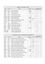
PB20
SJIT
Speed feedback filter time constant
Used to set the filter time constant of motor speed feedback.
Pt, Pr
S,T
0
~1000
0.1mS
PB21 NHF2
Machine resonance suppression filter 2
The second notch filter frequency to suppress the resonance.
Pt, Pr
S,T
10
~4000
Hz
PB22 NHD2
Machine resonance suppression 2
The second notch filter attenuation option
Pt, Pr
S,T
0
~32
dB
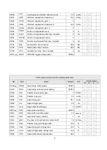
PB23
Reserved
PB24
VDC
Speed differential compensation
This function is valid when the PC signal activated.
Pt, Pr
S
0
~1000
-
PB25 NHF3
Machine resonance suppression filter 3
The third notch filter frequency to suppress the resonance.
Pt, Pr
S,T
10
~4000
Hz
PB26 NHD3
Machine resonance suppression attenuation 3
The third notch filter attenuation option
Pt, Pr
S,T
0
~32
dB
PB27 ANCF
Auto resonance suppression mode (for NHF1 and NHF2)
0
:
manual set
1
:
After a auto-scan then the resonance frequency is fixed.
2
:
Always auto-scan to search the resonance frequency.
Pt, Pr
S,T
0
~2
-
PB28 ANCL
Resonance suppression detection level
The high value setting denotes a less sensitivity detection.
Pt, Pr
S,T
1
~300
%
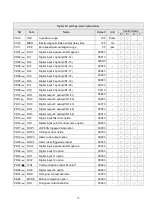
PB29 AVSM
Auto vibration suppression mode
0
:
manual set
1
:
After auto-suppression then the vibration frequency is fixed.
Note
:
When users set the PB29 as 1, the servo drive will find
the vibration frequency and suppress it, and the
frequency will be recorded to PB31, then the PB29 will
recover to
“0”.
Pt, Pr
S,T
0
~1
-
PB30
VCL
Low-frequency vibration detection level
The low value setting denotes high sensitivity detection. Users
set the proper value to prevent from erroneous detection.
Pt, Pr
1
~8000
pulse
PB31
VSF1
Vibration suppression frequency 1
To record the manual set or the result of auto-suppression. If
PB32 is 0, it denotes the 1
st
vibration suppression filter is off.
Pt, Pr
1
~3000
0.1Hz
PB32
VSG1
Vibration suppression gain 1
The high gain setting denotes a high position response. but
may cause a cogging motion.
Pt, Pr
0
~15
-
Summary of Contents for SDE Series
Page 13: ...5 1 6 Function block diagram ...
Page 26: ...18 3 3 3 CN1 pin name list ...
Page 223: ...215 SME L040 SME L075 SME L100 SME L150 ...
Page 224: ...216 SME L200 SME L300 SME M100 SME M150 Continuous running range ...
Page 227: ...219 ...
Page 231: ...223 4 Wiring example with peripheral equipment CN2 Encoder socket ...
Page 242: ...234 12 4 Version information Version V1 01 Issue date Aug 2017 Proofreader Yaochou Shu ...


