


50
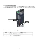
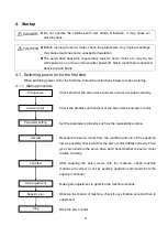
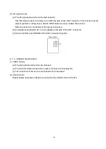
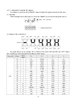
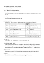
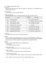
4.5.1. Indication of external I/O signals
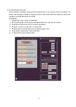
This display is used to verify the ON/OFF states of digital I/O signals connected to the drive.
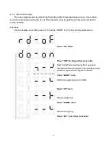
(1) Operation
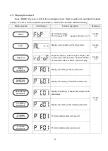
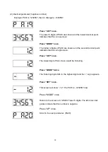
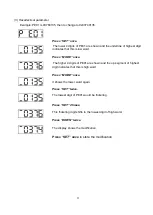
Call the display screen after power on. Press the
“MODE” key to show the diagnostic screen:
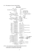
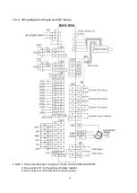
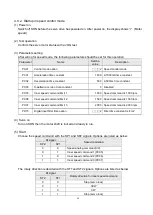
(2) Display of I/O pin definition
The figure above as an example: DI1 to DI8 are
“ON” status. DI9 and DI10 are ”OFF” status.
DO1 to DO5 are
“ON” status, DO5 and DO6 are “OFF” status.
Connector
Pin No.
Input/
output
Pt
Pr
S
T
CN1
12
I
TL1
POS4
TL
TL
13
I
CDP
POS5
CDP
CDP
14
I
SON
SON
SON
SON
15
I
CM1
POS1
SP2
SP2
16
I
PC
POS2
ST1
RS2
17
I
TL
CTRG
ST2
RS1
18
I
RES
RES
RES
RES
19
I
CR
CR
SP1
SP1
20
I
EMG
EMG
EMG
EMG
21
I
LOP
POS3
LOP
LOP
22
I
LSP
LSP
LSP
LSP
23
I
LSN
LSN
LSN
LSN
41
O
INP
INP
SA
WNG
42
O
ZSP
ZSP
ZSP
ZSP
43
O
CMDOK
CMDOK
MBR
MBR
44
O
TLC
TLC
TLC
VLC
45
O
RD
RD
RD
RD
46
O
ALM
ALM
ALM
ALM
Summary of Contents for SDE Series
Page 13: ...5 1 6 Function block diagram ...
Page 26: ...18 3 3 3 CN1 pin name list ...
Page 223: ...215 SME L040 SME L075 SME L100 SME L150 ...
Page 224: ...216 SME L200 SME L300 SME M100 SME M150 Continuous running range ...
Page 227: ...219 ...
Page 231: ...223 4 Wiring example with peripheral equipment CN2 Encoder socket ...
Page 242: ...234 12 4 Version information Version V1 01 Issue date Aug 2017 Proofreader Yaochou Shu ...


