


100
No
Abbr.
Function description
Control
mode
Setting
range
Unit
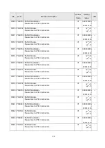
PD15
DIF
Digital input filter time option
0 0 0 x
x
:
filter time constant
0
:
invalid
1
:
2mS
2: 4mS
3: 6mS
4: 8mS
5: 10mS
Pt, Pr
S,T
0000h
~000
5
h
-
PD16
SDI
Digital input on/off control source option
Each bit of this parameter is to decide the on/off control source
of corresponding DI. The bit definition is described as follows.
0
:
The specified DI is controlled by the actual wirings.
1: The specified DI is controlled by communication software
Pt, Pr
S,T
0000h
~0FFFh
-
PD17 DOP1
LSP/LSN triggered stop option
0 0 0 x
x
:
motor stop option
0
:
stops immediately
1
:
decelerates to stop according to PF81 setting
Pt, Pr
S
0000h
~0001h
-
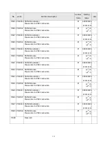
PD18 DOP2
CR signal clear option
As CR signal is activated, the deference between position
pulses and motor feedback pulses would be cleared.
0 0 0 x
x
:
clear option
0
:
CR rising edge trigger
1: keeps clearing while CR=1
2: As CR is triggered, the motor would decelerate to stop. The
remainder of pulse commands would be neglected. If
CTRG signal is triggered again, the present commands
would be executed. Here is the process chart.
Pt, Pr
0000h
~0002h
-
Summary of Contents for SDE Series
Page 13: ...5 1 6 Function block diagram ...
Page 26: ...18 3 3 3 CN1 pin name list ...
Page 223: ...215 SME L040 SME L075 SME L100 SME L150 ...
Page 224: ...216 SME L200 SME L300 SME M100 SME M150 Continuous running range ...
Page 227: ...219 ...
Page 231: ...223 4 Wiring example with peripheral equipment CN2 Encoder socket ...
Page 242: ...234 12 4 Version information Version V1 01 Issue date Aug 2017 Proofreader Yaochou Shu ...


