
133
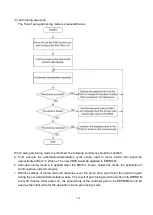
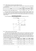
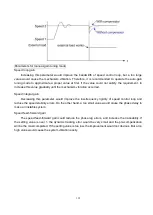
6.6. Speed control mode
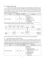
Speed control is often applied for occasions where is CNC machine, drilling machine, etc. The
command source is analog signal or inner register. The analog signal is the external voltage. The inner
command is performed by the following 2 ways: (1) Use the inner registers (PC05 to PC11) to set the
various commands then switch SP1, SP2, and SP3 to change the demand speed. (2)Use the
communication software to modify the value of speed command register.
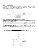
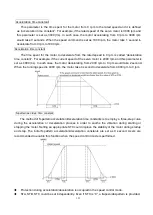
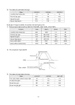
To avoid the discontinuity, the drives afford users the smooth S-pattern running. There are 2
control modes (manual and automatic) available. The manual mode enables users to set all related
parameters while the automatic functions were off. The automatic mode provides an estimation of load
inertia ratio and parameters adjusted. In addition, an simple mode is designed to provide users a robust
control which could instantaneously suppress external load interference. The basic speed control
blocks are shown as below.
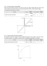
The S-pattern smooth process and speed filter are recommended to suppress the discontinuity.
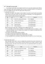
6.6.1. Selection of speed command
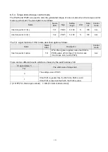
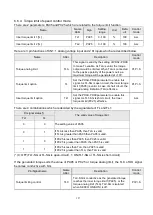
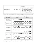
There are 8 combinations which are listed below for user to choose.
DI status
Valid
option
DI signal status(*)
Speed command
Setting range
Related
parameter
SP2
SP1
SP3 is invalid
(default value)
VCM
0
0
Analog Command(VC)
±10V
PC12
SC1
0
1
Inner speed command 1
-6000 ~ 6000
PC05
SC2
1
0
Inner speed command 2
PC06
SC3
1
1
Inner speed command 3
PC07
SP3 is valid
Valid
option
SP3
SP2
SP1
Speed command
Setting range
Related
parameter
VCM
0
0
0
Analog Command(VC)
±10V
PC12
SC1
0
0
1
Inner speed command 1
-6000 ~ 6000
PC05
SC2
0
1
0
Inner speed command 2
PC06
SC3
0
1
1
Inner speed command 3
PC07
SC4
1
0
0
Inner speed command 4
PC08
SC5
1
0
1
Inner speed command 5
PC09
SC6
1
1
0
Inner speed command 6
PC10
SC7
1
1
1
Inner speed command 7
PC11
(*) 0: OFF (SCx-SG is open-circuit) 1
:
ON (SCx-SG is short-circuit), x=1~7
Summary of Contents for SDE Series
Page 13: ...5 1 6 Function block diagram ...
Page 26: ...18 3 3 3 CN1 pin name list ...
Page 223: ...215 SME L040 SME L075 SME L100 SME L150 ...
Page 224: ...216 SME L200 SME L300 SME M100 SME M150 Continuous running range ...
Page 227: ...219 ...
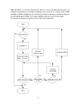
Page 231: ...223 4 Wiring example with peripheral equipment CN2 Encoder socket ...
Page 242: ...234 12 4 Version information Version V1 01 Issue date Aug 2017 Proofreader Yaochou Shu ...


