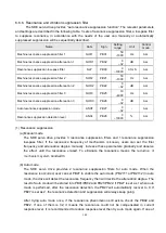
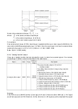
154
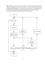
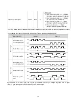
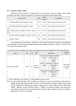
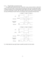
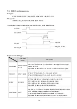
6.8. Control mode switch
SDE servo drives provide 5 modes switch to fit users who need to change varied modes
frequently. The PA01 could be changed for the control mode switch. See the table below.
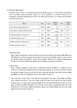
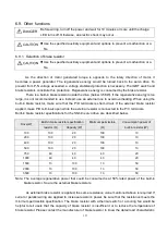
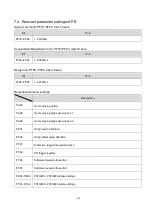
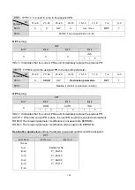
Control mode
Abbr.
PA01
setting
Description
Hy
brid
m
od
e
Position with external command - speed
Pt-S
1001h
Use DI signal to switch Pt and S
Position with external command - torque
Pt-T
1005h
Use DI signal to switch Pt and T
Position with inner register command - speed
Pr-S
1011h
Use DI signal to switch Pr and S
Position with inner register command - torque
Pr-T
1015h
Use DI signal to switch Pr and T
Speed - torque
S-T
1003h
Use DI signal to switch S and T
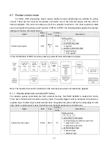
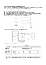
The arrangement of DI and DO is critical when the control mode switch is applied. To avoid DI/DO
pins insufficient, users could apply external analog voltage signal as speed or torque command so that
could reduce the demand of DI.
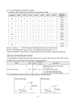
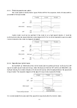
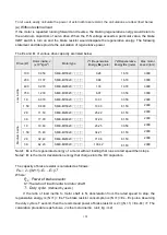
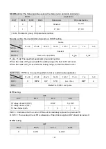
The LOP function should be made valid once control mode switch is applied. See the following table.
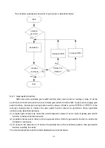
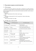
Name
Sign
I/O
CN1
No.
Description
Control
mode
Control mode switch
LOP
DI
CN1-21
(default)
Option of position/speed switched
LOP(*)
Control mode
0
position
1
speed
Option of speed/torque switched
LOP(*)
Control mode
0
speed
1
torque
Option of torque/position switched
LOP(*)
Control mode
0
torque
1
position
Described
by varied
case
(*) 0: OFF (LOP-SG is open-circuit), 1
:
ON (LOP-SG is short-circuit)
Note: The pin function setting of ST1 and RS2 are the same value, as speed/torque mode switch is
applied and the LOP signal activated, the ST1 function would have priority in speed control mode
and the RS2 function would have priority in torque control mode. Others such as POS1/SP2,
PC/ST1, RS2/PC, TL/ST2, ST2/RS1, RS1/TL, CR/SP1 are defined mutually. The drive would
automatically recognize the corresponding DI pin function when 2 different modes are switched.
See Section 3.3.4 for more details.
Summary of Contents for SDE Series
Page 13: ...5 1 6 Function block diagram ...
Page 26: ...18 3 3 3 CN1 pin name list ...
Page 223: ...215 SME L040 SME L075 SME L100 SME L150 ...
Page 224: ...216 SME L200 SME L300 SME M100 SME M150 Continuous running range ...
Page 227: ...219 ...
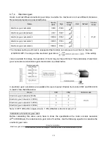
Page 231: ...223 4 Wiring example with peripheral equipment CN2 Encoder socket ...
Page 242: ...234 12 4 Version information Version V1 01 Issue date Aug 2017 Proofreader Yaochou Shu ...


