ADJUSTMENT
1 - 90
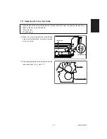
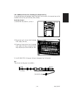
(6) Remove the SHAFT-TRAY.
(screws: 1 at the rear, 1 at the front)
(7) Install the COLLER-SFT-TRAY (2 pieces).
(5) Remove the following parts of the rear side
(refer to the figure on the right).
*
1 pusher
*
2 gears
GEAR (WHITE)
: 1 E-ring
GEAR (BLACK)
: 1 E-ring
PUSHER
: 2 screws
SHAFT-TRAY
COLLER
COLLER
Notes
*
When attaching the SHAFT-TRAY, Pay attention to whether it is facing the front or the rear (see below).
*
When attaching the gear, be careful to the direction of the gears. (See below; both should face in the
same direction)
A
A > B
Rear
Front
B
Summary of Contents for AR-650
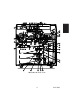
Page 103: ...MAINTENANCE 2 6 Rear drive system 38 36 37 3 54 54 54 54 54 54 96 12 81 63 63 46 ...
Page 104: ...2 7 MAINTENANCE ADF front sectional view 100 104 109 105 106 102 108 99 101 103 107 98 ...
Page 122: ...SUPPLIES 3 10 13 CONNECT 15 CLOSE 2 1 14 CLOSE 1 2 16 TURN ON 17 PRESS 18 END ...
Page 169: ...Click Finish button then Virtual Modem installation is completed 5 5 ...
Page 179: ...To make the connection ONLINE mode click button before firmware downloading 5 15 ...
Page 194: ......
Page 195: ...MEMO ...
Page 196: ...MEMO ...
Page 197: ...MEMO ...
Page 198: ...MEMO ...
Page 199: ...MEMO ...

