


1 - 57
ADJUSTMENT
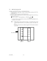
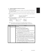
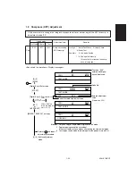
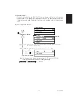
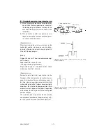
1.10 High-Voltage Adjustment
The charger and developer bias outputs must be checked and adjusted when the high-voltage transformer is
replaced.
Note 1:
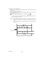
*1, *2 and *3 indicate sequence of operation patterns 1, 2 and 3, respectively.
Note 2:
BIT of *4 can be changed, however voltage is not output.
Note 3:
The BIT value of *5 must be entered by the digital keys.
Charger output
Image Mode
Adjustment
Value
Adjustment Method
Change the output by
changing the bit
states.
Input the BIT value of
210-0
*2
*3
*3
*1
*4
*4
*4
*5
*1
*1
*1
Code
210-0
210-1
210-2
212
Mode
PPC
PPC
PPC
TEXT/PHOTO
Text
Photo
------------
720
±
5V
↑
↑
↑
↑
↑
Item
Main charger
grid voltage
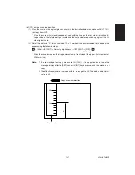
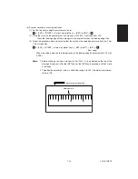
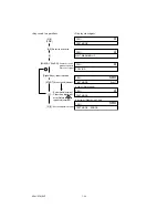
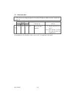
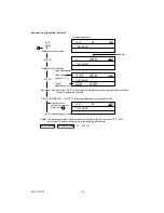
Developer bias output
Image Mode
Adjustment
Value
Adjustment Method
Change the output by
changing the bit
states.
Input the BIT value of
205-0
*2
*3
*3
*4
*4
*4
*5
Code
205-0
205-1
205-2
203
Mode
PPC
PPC
PPC
TEXT/PHOTO
Text
Photo
------------
387
±
5V
↑
↑
↑
↑
↑
Item
Developer bias
value Hi1
Developer bias
value Hi2
Developer bias
value Hi3
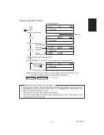
207
216
ALL
ALL
------------
------------
↑
↑
452
±
5V
Change the output by
changing the bit
states.
*4
Summary of Contents for AR-650
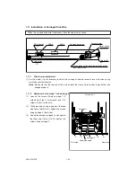
Page 103: ...MAINTENANCE 2 6 Rear drive system 38 36 37 3 54 54 54 54 54 54 96 12 81 63 63 46 ...
Page 104: ...2 7 MAINTENANCE ADF front sectional view 100 104 109 105 106 102 108 99 101 103 107 98 ...
Page 122: ...SUPPLIES 3 10 13 CONNECT 15 CLOSE 2 1 14 CLOSE 1 2 16 TURN ON 17 PRESS 18 END ...
Page 169: ...Click Finish button then Virtual Modem installation is completed 5 5 ...
Page 179: ...To make the connection ONLINE mode click button before firmware downloading 5 15 ...
Page 194: ......
Page 195: ...MEMO ...
Page 196: ...MEMO ...
Page 197: ...MEMO ...
Page 198: ...MEMO ...
Page 199: ...MEMO ...


