1 - 89
ADJUSTMENT
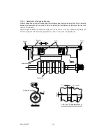
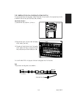
1.26 Additional Parts when Installing the Paper Exit Tray
To ensure perfomance of exiting-paper under all conditions, the parts used in the copier exit area for the
installation of the exit tray and the finisher differ as follows.
[Installation Method]
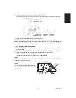
(1) Remove the lower exit cover (4 screws)
(2) Remove the rear E-ring, and slide the bearing
to the inside of the frame.
(3) Slide the exit roller to the rear and the bearing
to the inside of the frame, and remove the exit
roller while pulling out the exit roller rear side.
Exit cover
E-ring
Exit roller
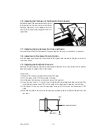
(4) Install RING-EXIT-24-UR (2 pieces) to the exit roller groove from the front side.
Note
*
The exit roller has the groove for installation.
RING-EXIT-24-UR
Exit roller
Rear
Front
Summary of Contents for AR-650
Page 103: ...MAINTENANCE 2 6 Rear drive system 38 36 37 3 54 54 54 54 54 54 96 12 81 63 63 46 ...
Page 104: ...2 7 MAINTENANCE ADF front sectional view 100 104 109 105 106 102 108 99 101 103 107 98 ...
Page 122: ...SUPPLIES 3 10 13 CONNECT 15 CLOSE 2 1 14 CLOSE 1 2 16 TURN ON 17 PRESS 18 END ...
Page 169: ...Click Finish button then Virtual Modem installation is completed 5 5 ...
Page 179: ...To make the connection ONLINE mode click button before firmware downloading 5 15 ...
Page 194: ......
Page 195: ...MEMO ...
Page 196: ...MEMO ...
Page 197: ...MEMO ...
Page 198: ...MEMO ...
Page 199: ...MEMO ...

