1 - 53
ADJUSTMENT
1.7
Automatic Adjustment of Gamma correction
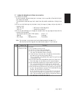
(1) At the time of unpacking
When the gradation reproduction deviation is too large, it can be corrected by the automatic adjust-
ment of gamma correction.
This adjustment shall be done upon user’s request when the gradation reproduction is too high or too
low.
(2) When any of the following parts are replaced, check the image and judge whether adjustment is
necessary or not.
• Exposure lamp
• Indicator unit with shading board
• Lens unit
• Laser optical system unit
(3) When any of the following parts is replaced or adjusted, check the copy image and determine the
necessity of this adjustment.
• Optical system position (CRG1, CRG2 position)
• Mirror 1, 2, 3
• Reflector
• Drum
• Developer
• Main charger
• Development bias
• Transfer/bias
Note:
This adjustment must be done only after the image adjustment described in 1.5.
After this adjustment, the image density adjustment described in 1.6 must be done.
Code
Adjustment item
Procedure
580
Automatic adjustment
of gamma correction
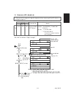
[Procedure]
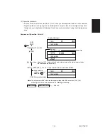
(1) Turn on the power switch with [0] [5].
(2) Select A3 or LD paper for the output paper size.
(3) Press the [2] key and then [ENERGY SAVER] key.
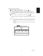
(One copy of the 33-gradation pattern is outputted.)
(4) Confirm that there is no blank or line on the gradation pattern outputted in
the above step (3) and the density changes gradually.
If there is any problem in the gradation pattern, repeat the step (3) to output
a gradation pattern again.
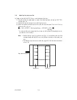
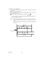
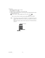
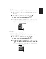
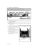
(5) Face the darker side of the output gradation pattern to the original scale at
the exit side and put it on the original glass with the printed face down.
(6) Input the code [580] through the control panel and press the [START] key.
(The scanner automatically reads the original and the operation for the
automatic adjustment of gamma correction will be done. About 10 seconds)
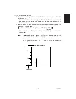
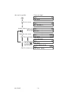
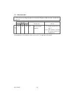
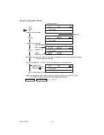
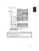
(7) When the operation completes normally, the machine returns to the stand-
by status. If the operation ends abnormally, “TEST MODE ERROR” will be
displayed. (See the indication on the next page.)
For the abnormal ending, press the [C] key to release the error indication.
When released, the display on the control panel returns to the stand-by
status. Check the position, direction and skew of the gradation pattern on
the original glass, and repeat the steps from (5).
Summary of Contents for AR-650
Page 103: ...MAINTENANCE 2 6 Rear drive system 38 36 37 3 54 54 54 54 54 54 96 12 81 63 63 46 ...
Page 104: ...2 7 MAINTENANCE ADF front sectional view 100 104 109 105 106 102 108 99 101 103 107 98 ...
Page 122: ...SUPPLIES 3 10 13 CONNECT 15 CLOSE 2 1 14 CLOSE 1 2 16 TURN ON 17 PRESS 18 END ...
Page 169: ...Click Finish button then Virtual Modem installation is completed 5 5 ...
Page 179: ...To make the connection ONLINE mode click button before firmware downloading 5 15 ...
Page 194: ......
Page 195: ...MEMO ...
Page 196: ...MEMO ...
Page 197: ...MEMO ...
Page 198: ...MEMO ...
Page 199: ...MEMO ...


