


1 - 59
ADJUSTMENT
100%
A4
A
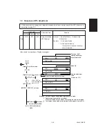
[0] [5]
[PWR]
[START]
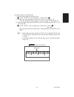
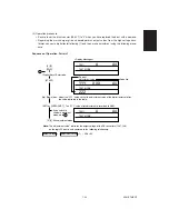
[SET] or [INTERRUPT]: The “YYY” value after adjustment is recorded to NVM.
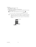
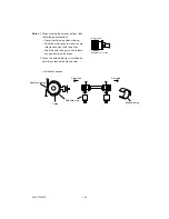
Note:
The “adjustment value” indicates the output voltage of the DA converters (IC47, 148)
on the logic PC board, and conforms to the following relationship:
output voltage = ( adjustment value + 1)
÷
256
×
5V
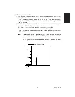
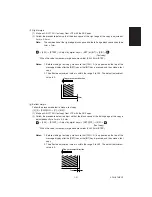
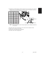
[Up] [Down] icon: Adjust the “YYY” value so that the adjustment value of the digital tester satisfies
the value indicated in the table.
If you switch to
another adjustment
mode, go to .
[0] [9]
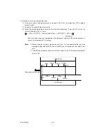
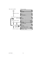
[Digital Keys]: Enter code.
1
: Exit adjustment mode.
1
Code No.
<Display Messages>
TEST MODE
100%
A4
A
TEST MODE
YYY
ZZZ
A4
XXX
TEST MODE
Current
adjustment value
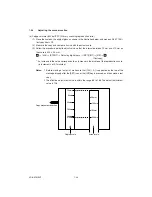
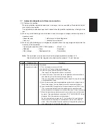
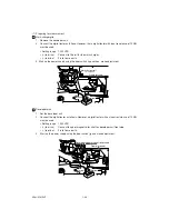
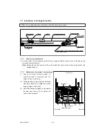
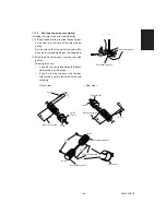
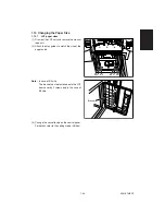
(2) Operation procedure
• Be sure to set the drum counter (08-401) to “0” when you have replaced the drum with a new one.
• Regarding the main charger grid and developer bias output values from the high-voltage trans-
former, connect a digital tester following (1) and then, make adjustment using the following proce-
dure.
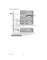
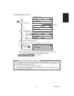
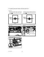
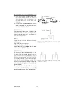
Sequence of Operation, Pattern 1
Summary of Contents for AR-650
Page 103: ...MAINTENANCE 2 6 Rear drive system 38 36 37 3 54 54 54 54 54 54 96 12 81 63 63 46 ...
Page 104: ...2 7 MAINTENANCE ADF front sectional view 100 104 109 105 106 102 108 99 101 103 107 98 ...
Page 122: ...SUPPLIES 3 10 13 CONNECT 15 CLOSE 2 1 14 CLOSE 1 2 16 TURN ON 17 PRESS 18 END ...
Page 169: ...Click Finish button then Virtual Modem installation is completed 5 5 ...
Page 179: ...To make the connection ONLINE mode click button before firmware downloading 5 15 ...
Page 194: ......
Page 195: ...MEMO ...
Page 196: ...MEMO ...
Page 197: ...MEMO ...
Page 198: ...MEMO ...
Page 199: ...MEMO ...


