40
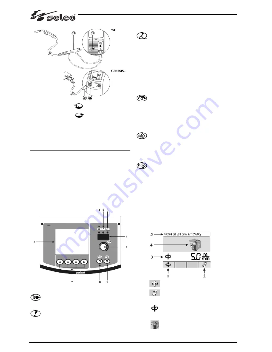
- Connect the red colored
water pipe of the torch to the
inlet quick connector of the cooling unit.
- Connect the blue colored
water pipe of the torch to the
outlet quick connector of the cooling unit.
- Connect the MIG torch (23) to the central adapter (24), ensur-
ing that the fastening ring is fully tightened.
- Connect (25) the earth clamp to the negative socket (-) (26) of
the power source.
3 SYSTEM PRESENTATION
3.1 General
They are fully digital multiprocessor systems (data processing on
DSP and communication over CAN-BUS), capable of meeting
the various requirements of the welding world in the best pos-
sible way.
The presence of a powerful microprocessor allows full control of
all the welding functions, making this system suitable for various
types of welding process such as MMA, TIG DC LIFT START,
MIG/MAG.
3.2 Front control panel
1 Power
supply
Indicates that the equipment is connected to the mains
and is on.
2 General
alarm
Indicates the possible intervention of protection devices
such as the temperature protection (consult the “Alarm
codes” section).
3 Power
on
Indicates the presence of voltage on the equipment
outlet connections.
4 7-segment
display
Allows the general welding machine parameters to be
displayed during start-up, settings, current and voltage
readings, while welding, and encoding of the alarms.
5
LCD display (3.5"/4.7")
Allows the general welding machine parameters to be
displayed during start-up, settings, current and voltage
readings, while welding, and encoding of the alarms.
Allows all the operations to be displayed instantaneously.
6
Main adjustment handle
Allows entry to set up, the selection and the setting of
the welding parameters.
7
Processes/functions
Let you select the various system functions (welding
process, welding mode, current pulse, graphic mode,
etc.).
8 Synergy
Lets you select a preset welding program (synergy) by
choosing a few simple settings:
- wire type
- gas type
- wire diameter
9 Programs
Allows the storage and management of 64 welding
programs which can be personalised by the operator.
3.3 Starting Screen
When switched on, the generator performs a succession of
checks in order to guarantee the correct operation of the system
and of all the devices connected to it.
At this stage the gas test is also carried out to check the proper
connection to the gas supply system (system for automation and
robotics).
3.4 Test screen
When the side panel (coil compartment) is open, the welding
operations are inhibited.
The test screen appears on the LCD display.
1
Wire feed
2
Gas test
3 Wire
speed
Allows the regulation of the wire feed rate.
Minimum 1 m/min, Maximum 22 m/min,
Default 1.0m/min
4
Side panel open
Summary of Contents for Genesis 4000 MSE
Page 32: ...32...
Page 62: ...62...
Page 212: ...212...
Page 242: ...242...
Page 272: ...272...
Page 302: ...302...
Page 332: ...332...
Page 336: ...336 1 3 1 4 11 35 1 5...
Page 338: ...1 8 IP S IP23S 12 5 mm 60 2 2 1 2 2 10 2 3 400V 230V V 230 400V 338...
Page 339: ...339 15 15 2 1 5 2 4 MMA 3 4 1 2 WF ARC AIR 5 6 7 ARC AIR 8 9 TIG 10 11 TIG 12 13 14 15...
Page 341: ...341 8 9 64 3 3 3 4 LCD 1 2 3 1 m min 22 m min Default 1 0 m min 4 5 3 5 MMA TIG DC MIG MAG...
Page 354: ...5 6 Reset 354...
Page 355: ...355 encoder...
Page 356: ...356...
Page 357: ...357 7 7 1 MMA Hot Start Arc Force antisticking 7 2 TIG TIG Tungsten lnert Gas 3370 C H F lift...
Page 359: ...359 7 3 MIG MAG MIG SHORT ARC 1a SHORT a SPRAY ARC b SPRAY ARC 1b 2 3 2 3 1a 1b...
Page 366: ...366 GENESIS 4000 MSE 3x230 400V...
Page 367: ...367 GENESIS 4000 MSE LCD 3 5 LCD 4 7 3x400V...
Page 368: ...368 GENESIS 4000 MSE LCD 3 5 LCD 4 7 3x230 400V...
Page 369: ...369 GENESIS 5000 MSE 3x400V...
Page 370: ...370 GENESIS 5000 MSE LCD 3 5 LCD 4 7 3x400V...
Page 372: ...372 GENESIS 4000 MSE LCD 3 5 LCD 4 7 3x400V GENESIS 4000 MSE LCD 3 5 LCD 4 7 3x230 400V...
Page 373: ...373 GENESIS 5000 MSE 3x400V GENESIS 5000 MSE LCD 3 5 LCD 4 7 3x400V...


