background image


Be aware that if you've got your objects grouped, clicking on 

Copy

 will result in the entire

group being copied. 


The 

Remove

 button works as you'd expect.  Select an object and click 

Remove

 to 

remove it from the virtual build surface.


Cancel

 will discard any changes you've made so far and 

Save 

will allow you to save the 

state of the virtual print surface.  Saving your work saves it to the print queue.  If you'd like to 
save your work as a combined STL file


While you're in edit mode, there's a series of commands that

become available along the right edge of the 3D View pane. 


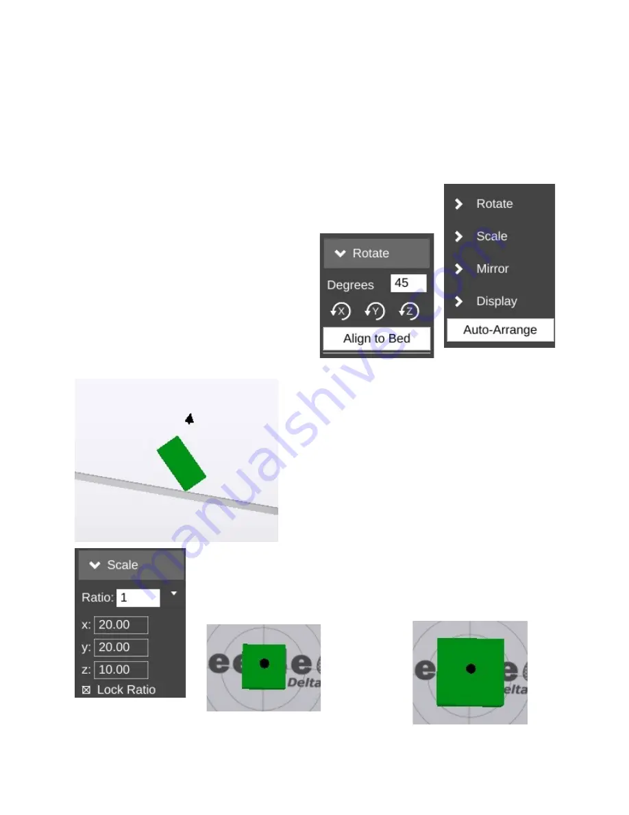
Unlike normal manual positioning, the 

Rotate

 function allows you to specify the exact

rotation of the object along its X, Y, and Z axes.


In order to change the orientation of the

object, simply enter the value you want in the 

Degrees

 field and then click the axis you want to

apply that value to.  Below is an example of what
the example cube looks like after rotating it 45
degrees along its X axis.

  Being able to re-orient the part on the build surface 
can be handy to have, especially if you're dealing with 
a part that was saved in a position that didn't lend itself
to easy 3D printing. 

  Clicking 

Align to Bed

 will automatically orient the 

nearest flat surface to the virtual build platform.


The 

Scale

 function will allow you to change the width, height and 

length of the part or parts currently on the virtual build platform.


The 

Ratio

 field allows you to shrink or grow an entire model by a 

specific percentage.  For example, if you were to change the 

Ratio

 from 1

to 1.5, you'd see this:

Become this:

90

Summary of Contents for orion delta

Page 1: ...asoft com Licensed as Creative Commons Attribution ShareAlike 3 0 This guide will take you through the steps to set up and operate your new 3D printer from SeeMeCNC You ll find instructions on calibration software maintenance and more all in this manual As a new SeeMeCNC owner you ll also find a ton of great resources on the forums at forum seemecnc com 1 ...

Page 2: ...matic machine can start unexpectedly Pay close attention and keep clear while power is connected to the machine The machine power supply is connected to AC voltage and can be hazardous Disconnect power before servicing this machine The hot end of the machine can reach very high temperatures of 700F and can cause serious burns The heated print surfaces heated bed can also reach temperatures high en...

Page 3: ...ng your new Orion Delta 3D Printer The Easy Way 27 A Simple Guide to Hot End Priming 32 Printing from the SD Card 34 Changing Filament 37 Printing From Your Computer 40 MatterControl Basics Slicing 48 MatterControl Basics Loading and Printing an Object 61 Advanced MatterControl Configuration 67 Advanced MatterControl Settings Print 71 Advanced MatterControl Settings Filament 81 Advanced MatterCont...

Page 4: ...r Before downloading the First Edition please make sure that you actually need it Compare the LCD idle screen shown on power on after the initialization sequence takes place on your machine to the first LCD screen photo shown in the The LCD Control Panel chapter If they match you ve got the newer firmware and do not need the second edition You can follow this edition to reach the power on point in...

Page 5: ...seam in the box After you ve cut the tape open the top of the box being careful of any packaging staples You ll find the machine tucked inside and wrapped in a protective expanding foam shell Remove the machine and foam all as one by pulling straight up out of the box Be careful not to drop the machine once it s out of the box and the foam is still around it 5 ...

Page 6: ...and remove the stretch wrap film that is holding the power USB cables Orion control panel and accessories on the top plate as well as the stretch wrap holding your filament to the table top and glass build surface 6 ...

Page 7: ...r the bed by lowering the delta arms as low as they ll go on each tower These arms need to be raised in order for the Orion Delta to be used The process is very simple just grasp the Cheapskate bearing for each arm and raise them one at a time to the top of the Orion as shown in the photos below 7 ...

Page 8: ...t the hot end in the operation position you ll need to remove the tape that covers the end stop switches as shown below This tape helps prevent damage to the end stop switches when the packing film is being removed 8 ...

Page 9: ...ur Orion Delta will likely differ from the photos shown here but the installation instructions are identical Gently pull the pair of flat ribbon cables out a bit from the Orion Delta and install them as shown The first cable is marked by an X and has a matching X on the back of the LCD controller 9 ...

Page 10: ...do most calibration standalone without the USB cable attached We recommend hooking it up now so if you need to connect it to your computer to make changes etc the cable is already installed Pass the end of the USB cable up through the hole in the bottom left of the base and plug it into the USB input on the electronics board 10 ...

Page 11: ...l the two black thumb screws and tighten them finger tight Remove the two black thumb screws as shown and set them aside Now you ll install the LCD control panel into the Orion Delta Please take care as the parts are a tight fit Align the LCD mounting plate as shown below there s small locking tabs that fit into the slots shown 11 ...

Page 12: ...lush against the mating surface making sure that not wires get pinched between the two panels this is a tight fit so please be careful Insert the black thumbscrews you d removed earlier in the mounting holes and tighten them using only your fingers 12 ...

Page 13: ...In the accessories box you should find a small SD card Insert the SD card into the side of the LCD enclosure as shown below 13 ...

Page 14: ... and Spool Holder In order to reach the power supply you ll need to remove the panel that covers it Remove the two black thumb screws and set them and the panel aside Get the power cable from the box the accessories came in 14 ...

Page 15: ...er supply to its 240V setting This switch is located right below the power socket as shown You can use a flat tip screwdriver to change its position The power cable is installed by routing it through the hole in the base of the Orion Delta and plugging it into the socket on the power supply It s a tight fit so take your time 15 ...

Page 16: ...ow replace the door as shown replacing the black thumbscrews you d removed previously As with the others tighten them only with your fingers The spool holder is made from two identical laser cut parts 16 ...

Page 17: ... spool holder parts together install in the spool holder mount as shown Press down firmly once the hooks on the spool holder are fully inserted into the mounting holes This will lock the spool holder into place 17 ...

Page 18: ...e sure that the filament is oriented such that the filament comes off the top of the spool not the bottom Route the filament through the first filament guide as shown and then route the filament through the second filament guide that s located on the other side of the rear tower 18 ...

Page 19: ...rough the EZStruder you ll need to depress the red lever with your thumb press up and thread the filament in from the bottom as shown Continue to feed filament until the filament enters the hot end through the bowden tube 19 ...

Page 20: ...Finally you ll want to remove the protective plastic sheet that covers the LCD 20 ...

Page 21: ...ng outlet Orient the Orion Delta to face you and flip the power switch to the right You should be briefly greeted by a power on message similar to the one shown below After a short delay the front page of the LCD should be displayed Now that you ve got your Orion powered up let s learn what it s all about 21 ...

Page 22: ...It reads degrees Celsius you ll quickly find that just about everything to do with 3D printing is done in Metric units of measure FYI 17 5C is 63 5F 2 Bed Temperature This is the temperature of the heated bed as measured by the thermistor in the center of the bed Just like the nozzle it reads in degrees Celsius 3 Speed Rate This is the speed multiplier field Normally it will read 100 but if you ve...

Page 23: ... temperature display like the example below In the image above the hot end temperature has been set to 200 degrees Celsius and the bed has been set to 90C Note that just about all aspects of 3D printing is expressed in metric or SI units You ll notice an additional line at the bottom of the LCD display this is a message line and the firmware in your Orion Delta will display information relevant to...

Page 24: ...rinter Settings as below Press the knob in to select the Printer Settings menu Your LCD should now show the following menu Rotate the knob to the left and select the Home Towers option Pressing the button should result in your Orion Delta homing all three axes Note that if you leave the LCD in menu mode for too long it will automatically revert to the home screen 24 ...

Page 25: ... to close to printing temperature to let any heat expansion take place To do so click on the knob and scroll to Printer Settings then Preheat ABS and press the knob This will set the heated bed to 90c and the hot end to 200c This is less than the melt temp for ABS but a good holding temperature that will make sure that any ABS filament doesn t burn as it sits in the hot end waiting for the bed to ...

Page 26: ...so that the nozzle tip is about 1 2 above the glass build surface Make sure the nozzle is clean and there is no filament hanging from the nozzle Be careful it s hot now Take a single sheet of notebook paper and place it under the nozzle Turn the knob slowly and jog down until the nozzle just begins to snag on the paper Now press the knob to return to the menu and scroll down to Set new Z 0 00 to s...

Page 27: ...written by the gentleman that built and calibrated your printer so there literally is no more authoritative source for the process 1 Preheat hot end and bed to the material you use If you use both just use the Preheat ABS in the printer settings menu on the LCD 2 Once the hot end and bed are up to temp on the LCD click the knob to bring up the menu go to Advanced Settings at the bottom of the list...

Page 28: ...the following pic 7 Turn the knob counterclockwise SLOWLY and look eye level with the bed and bring the nozzle down till it just barely meets the glass this is easiest with a white wall in the background so you can watch the reflection of the nozzle if you don t have a white background to use you could tape a sheet of paper between the towers to give you enough contrast When the nozzle touches the...

Page 29: ...ATIONS sub directory Then chose the TOWERS GCO file This will run the tower calibration routine Watch closely as the machine will home then the nozzle will drop to 0 2mm ABOVE the glass The gap will look like the following image After it drops to the center position it will travel to the X tower DO NOT pay attention to what the nozzle does while traveling what you must pay attention to is when it ...

Page 30: ...he tower RAISES compared to the CENTER you want to adjust the screw that hits the end stop by turning it counterclockwise moving the screw up If the nozzle at the tower LOWERS compared to the CENTER you want to adjust the screw that hits the end stop by turning it clockwise moving the screw down Pic of screw you will adjust Make small changes to the screw about 1 8 turn adjustments 11 After you ha...

Page 31: ...e outer edges where the nozzle pauses 13b If from the center gap the nozzle goes UP away from the glass at ALL 3 TOWERS load your host software and bring up the EEPROM information You will look for Horizontal Radius You want to LOWER that number I suggest raising it by 0 2 and run towers gcode to see the change and keep raising the number till the gap evens out changing this number will not make y...

Page 32: ... hand in order purge the hot end Now go to the menu and select Adjust Temps then scroll down to Temp 0 and click then set the temp to 215 and click to set the new hot end temperature You can wait for the screen to go back automatically to the main screen or scroll up and click Back and get to the home screen Once the hot end is up to temperature reach around the right side and rotate the knob on t...

Page 33: ...That s all there is to it You re ready to print 33 ...

Page 34: ...lot in the blue acrylic side panel as shown below If you ve got an SD card reader on your computer you can easily save files to the SD card in order to print with your Orion Delta in stand alone mode You don t need to connect the printer to your computer in order to print Let s take a look at the demo files that were included on the SD card that was shipped with your Orion Delta Click the control ...

Page 35: ...ther files on the SD card Click the GCODE directory to see a list of the files included For this first print go ahead and click on the file BLINKY GCO When you select the file name the LCD controller will make a chirping sound and the heated bed will begin to heat up Once the bed has reached its target temperature the printer will home all three axes and then the hot end will begin its heating pro...

Page 36: ...ic to stick to the glass Apply the glue stick in a thin layer of parallel lines Let it dry and repeat the process using lines perpendicular to the first layer Once it dries you can print Do NOT apply the glue stick to a hot bed If you need to cancel a print job for any reason simply turn the machine off and use the control panel to re home the towers 36 ...

Page 37: ...you re printing Once the hot end is at operating temperature pop the bowden tube off the hot end as shown in the following steps 1 Grip the bowden tube with one hand and press down the blue ring and pull up on the bowden tube You may need to depress the red release lever on the extruder in order to get enough slack to pull the bowden tube free of the hotend fitting 37 ...

Page 38: ...When the filament pulls free it should look something like the photo below 2 Cut off the filament flush with the end of the bowden tube 38 ...

Page 39: ...ll the filament stub from the hotend and then re insert the bowden tube into the hotend making sure it seats fully Here s a video that covers the process nicely https www youtube com watch v jbS0CCr8USQ 39 ...

Page 40: ... printer among other things is called MatterControl From now on I ll refer to it simply as the host software or some cryptic variant of that You can download MatterControl by going to the SeeMeCNC website http seemecnc com pages downloads Scroll down to the Software heading and you ll see the links for MatterControl Download the version for your platform and install it Start MatterControl Below yo...

Page 41: ... the Add icon as indicated by the blue arrow Clicking on the Add icon will open up the 3D Printer Setup dialog Here is where you ll name the new printer configuration and where you select your printer model So go ahead and enter a printer name and then chose Orion from the Select Model list Once you ve done this the Save Continue button will appear at the bottom left corner of the window Click on ...

Page 42: ...on Install Driver Once you ve given permission to run the installer the following dialog will appear Click on the Install button to install the driver When the installer is finished MatterControl will continue on to auto detect the printer Make sure that you ve got your Orion disconnected and then click Continue 42 ...

Page 43: ...done Click on the Done button to continue At this point your MatterControl screen should look something like this The configuration process automatically loads a test object that you can print Let s take a few minutes to go over the various features of the MatterControl interface 43 ...

Page 44: ...ater 5 Print History This will show you what you ve printed in the past along with statistics about each print 6 About This gives you information about the fine folks that created MatterControl It also includes a button to send them feedback as well as a button to check to see if any updates are available 7 Advanced Controls this is where you can manually control the printer We ll cover this later...

Page 45: ...s been sliced 2 View manipulation controls Rotate Pan and Zoom By default the 3D view will show a rotating display of the part You can stop the rotation by clicking anywhere in the 3D view window 3 The object currently ready to print 4 This is a representation of your Orion s print bed As long as your object fits within the circle you can print it 5 6 The Insert and Edit buttons allow you to add a...

Page 46: ... in this guide Now click Print button at the top of the display to start the print job You ll notice right off that the display changes to show you what s going on The status window will tell you what MatterControl thinks the print time will be as well as a progress bar along the bottom that gives you the actual percentage completed 0 7 in the example below Your Orion LCD will show you that the ho...

Page 47: ...gratulations on your first successful print Let the bed cool to room temperature and you should be able to pop the cube right off the bed without any problems This has been a warp speed introduction to MatterControl In the next section I ll cover MatterControl in some detail and we ll print one of the files included on the SD card that was shipped with your new Orion 47 ...

Page 48: ...yers basically the model height divided by 0 2mm For a tall part this can mean a LOT of layers MatterControl provides three slicers for your use MatterSlice CuraEngine and Slic3r This guide will only cover the specifics of MatterSlice but don t let that stop you from experimenting with and using the other slicers I ll show you how to change the slicing engine later on in this guide The final task ...

Page 49: ...ngs for right now There s a LOT that goes on to configuring your slicer and the Simple configuration setting allows many of those to be hidden until you re more comfortable with how your printer works Layer Height This parameter tells the slicing engine how thin to make the layers when it slices up the model as I described earlier A good default layer height is 0 2 or 0 25mm The lowest practical l...

Page 50: ...uick you could go up to a 0 35mm layer height I wouldn t recommend anything over 0 40mm if you re using a 0 5mm nozzle however Fill Density This parameter controls how solid your printed part is The number is a percentage from 0 totally hollow to 1 totally solid The default fill density also known as infill is 0 2 or 20 The image below shows what that looks like inside our little test cube You can...

Page 51: ...ple if you re printing a part that sits on small feet a raft would come in handy if the initial layers of the feet don t stick very well In the image below you ll see an example of both support material and a raft I took the little test cube and through a little manipulation printed it tilted at 30 degrees I took this opportunity to also demonstrate what a raft looks like This one is exaggerated i...

Page 52: ...ugh of it there to handle the actual print layer that it will be supporting In my example the support material has a 2 5mm spacing between the walls of support material and it uses an infill angle of 45 degrees The printed part will usually separate from the support material fairly easily however some material will be left behind if you re using a raft Cleaning up the left over support material is...

Page 53: ...n see there s still a little clean up to to be done to the printed cube on the left A quick hit with some 220 grit sandpaper will knock the rough edges of the support material down That s pretty much all there is to the Simple settings level Next let s dig into the Intermediate setting 53 ...

Page 54: ... Perimeters setting This setting is often called shells because it controls how thick the skin of your printed object is going to be The default is 2 perimeters On the left is an example of what two perimeters look like When the cube is being printed the 2 perimeter is printed first and then the 1 perimeter The order is configurable In the image below you can see what those perimeters actually loo...

Page 55: ... the Skirt can become a Brim if the Distance from Object setting is set to zero What this does is make sure that the skirt is physically connects to the part becoming a brim This can be handy when you re printing a small part and you re having bed adhesion issues and you don t want to have to use a raft Later on in the Advanced settings section you ll see more options on how you can tweak the Skir...

Page 56: ...C WITH THE STOCK HOT END THAT S SHIPPED WITH THE ORION The reason for this is because of how the stock hot end is designed It uses a PEEK section a high temperature plastic as the cold end of the hot end This material will begin to fail at 247C If you need to print with a high temperature filament such as Nylon it s highly recommended that you purchase an all metal hot end Bed Temperature Like the...

Page 57: ... configuration In this example I ve named it after the vendor the material color and the date I purchased the material Since this is the first time I ve used this material the only thing I know for sure is what the average filament diameter is To enter that I picked Filament from the Select Category drop down then from the Select Group drop down Filament was chosen again and finally Diameter was s...

Page 58: ...on as shown below Clicking on the button will open up the materials editor and allow you to change the temperature It s as simple as that The last new category exposed by the Intermediate mode is called Printer This category deals with the physical properties of the printer itself Because you chose the specific printer model you have when you first set up MatterControl all the basic parameters hav...

Page 59: ...t the print quality of your model in the QUALITY presets Things like layer height print speed etc MATERIAL presets should only contain those settings that directly deal with the material you re using to print the current object with You ll find that both the QUALITY and MATERIAL presets contain more options than I ve covered here Those new options are exposed by choosing the Advanced settings leve...

Page 60: ...s indicating the step distance from 0 1mm to 100mm The selected axis will move the selected step distance with each mouse click For this reason please take special care when you ve got 100mm set for the step distance The Orion is smart but not THAT smart It relies upon you to not put the poor thing in an unlikely position The last set of buttons control the extruder motor they re marked E and E an...

Page 61: ...3D printer slicing programs can read a file format called STL You can learn more about this file format including its origins here http en wikipedia org wiki STL_ 28file_format 29 When you download a file from Repables or one of the other free online object repositories you ll often get the file as a zip file One nice feature of MatterControl is the ability to select a zip file and MatterControl w...

Page 62: ...I ve decided to leave the QUALITY setting at Coarse and I m using the tweaked material values that I set up earlier Because the key chain is pretty large I m going to scale it down to 75 of it s original size This is an easy task in MatterControl Click on the Edit button as shown above This will modify the 3D View so the edit controls are visible 62 ...

Page 63: ...Save button at the bottom of the window This will allow you to save the object under a different name if you don t want to over write the original Before we start this print let s take a second to examine a feature of MatterControl the Layer View If you ve not sliced this object yet you ll like see the text Press generate to view layers Go ahead and do that now 63 ...

Page 64: ...64 ...

Page 65: ...he bottom of the window you ll see some controls that will allow you to either re slice the object Generate or view the individual print layers The controls will show you how many layers are on this object as well as what the layer number is that you re currently viewing You can navigate forward and backward through the layers by using the and buttons If you want to jump to a specific layer you ca...

Page 66: ...handy information if you re selling your services and need to know how much a particular part is going to consume in both time and materials Go ahead and click the Print button and get your object printing After the print finishes you should have a little part that looks something like the photo below if that s what you printed 66 ...

Page 67: ...OT calibrate a delta printer What it can do is help improve first layer performance on an already calibrated printer SeeMeCNC has put together a nice video that illustrates the process quite effectively https www youtube com watch v z6ymbr AMew The EEPROM Settings configuration option will allow you to edit firmware parameters that are stored on the controller inside your Orion Please take special...

Page 68: ...e displays In order to be able to use the terminal for basic tasks you ll need to click on the Filter Output check box that s at the upper left corner of the window This will filter out the telemetry information coming from the Orion s controller and allow you to directly interact with the printer without having the output interleaved with the periodic information that the Orion transmits MatterCo...

Page 69: ...Feed configuration option allows you to choose which type of release you want to be notified about when there s an update Stable releases are tested and generally recommended for all users The Beta release level represents versions of MatterControl that are in a pre release state but testing is ongoing Use this release level if you enjoy assisting the MatterControl software development team find b...

Page 70: ...ange the options available on the Settings pane but shouldn t disturb those you ve changed in the past The MatterControl team has tried to keep common names across slicing engines so the most noticeable change you ll see will be additional options supported by one slicer but not the others Theme Display Options allows you to change the primary color that the user interface renders in The top row o...

Page 71: ...ts that relate to how the plastic is laid down Filament covers parameters specific to the type of filament that you ve chosen to print with Printer handles those remaining parameters that describe the physical printer you re currently using to print with This section will cover Print Let s start this overview on the main page of Print Layers Perimeters 71 ...

Page 72: ...m the bottom of the model For example say you ve got a 200mm tall model but you only want to print the top 50mm or so You can enter 150 into the Bottom Clip field and when the slicer generates the G code for the print job it will begin slicing 150mm up from the bottom of the model Perimeters dictate how thick the skin of your model is 2 or 3 perimeters are good for most parts but if you want a rea...

Page 73: ... getting a lid that you ll have to cut off By default objects are printed from the inside features to the outside If you want to reverse this process enable External Perimeters First This will cause the outside of the model to be printed before the interior features The Top and Bottom solid layer parameters dictate how thick the top and bottom surfaces of your object are when printed These two par...

Page 74: ... Now if you change the starting angle to 45 degrees you ll end up with an infill pattern that looks like the example below Note that changing the starting angle will also change the angle in which the top and bottom layers are printed You can see this in the image below this shows the second layer as it would be printed Infill Overlap is used to adjust how well the infill pattern attaches to the i...

Page 75: ...u re going A skipping extruder has a very distinct sound it s kind of a light bump or knocking If you watch the nylon gear that you use to manually feed filament you ll notice that it will briefly rotate in the opposite direction at the same time you hear the skipping sound If you draw a line on the face of the gear you can spot this motion more easily The skip is caused by the hot end s inability...

Page 76: ... Distance from Object parameter dictates how far away the loop stands off from the part outline If you set the distance to zero the skirt will become a brim It will result in the loops being printed connected to the first layer of your print This can give small parts a first layer that has a larger surface area to improve part adhesion Since the brim is only a single layer thick it s usually prett...

Page 77: ...ype selection allows you to define the geometric pattern for the support structure You have GRID and LINES These patterns were covered earlier so I won t cover them again here The new parameter you have to work with in Advanced mode is called Amount Amount is expressed in degrees from vertical and tells the slicing engine to generate support for any feature that meets or exceeds the specified angl...

Page 78: ...y be in contact with the PVA interface layers and it would be a flat layer to print on When finished you can dissolve away the interface layers and the rest of the support falls off the part cleanly X and Y Distance dictates how far away the support structure will be from the part you re printing You want it as close as you can get it without it actually touching the surface of the part The defaul...

Page 79: ...ions page is a single parameter Center On Bed This will automatically center the model on the print bed when you load it If you don t want that to happen just uncheck the box The Multiple Extruders page has two settings that control how ooze filament wipes are handled The Wipe Shield Distance specifies how far away from the part you want what is commonly known as an ooze shield to be placed around...

Page 80: ...sion width of the first layer A first layer width that s larger can help with how the material adheres to the bed You can specify it as either an actual width or as a percentage of the normal extrusion with typically the same as the nozzle diameter Support Material allows you to specify how wide you want the extrusion to be for the support structure if you re using it 80 ...

Page 81: ...d using the filament as part of the material profile name Note the date on the spool label if it has one and add one if it doesn t This will help you track individual spools of the same color and manufacturer The Extrusion Multiplier parameter allows you to tweak the flow rate of the material coming out of the hot end A basic rule of thumb on this is to restrict the max value to 1 1 and the minimu...

Page 82: ...lp prevent blobbing Minimum Travel Requiring Retraction is used to prevent retractions during very short moves when retraction isn t really necessary When executing a non printing move the nozzle will have to travel at least this distance in order to trigger a retraction action Finally Minimum Extrusion Requiring Retraction specifies how much filament must be extruded before a retraction operation...

Page 83: ...d time to print the slicing engine will automatically slow the print speed down to meet this goal This can be important because if you don t use a fan a layer will need time to radiate its excess heat before the next layer is applied If the material isn t cooled or given time to cool via radiation heat can build up in the underlying layers and cause curling and other undesirable effects Minimum Pr...

Page 84: ...it s created by the slicing engine The Bed Shape parameter dictates what bed type is shown in the 3D viewer The Hardware section allows you to specify what features are installed on your Orion Has Fan when checked will allow the slicing engine to control the layer cooling fan Has Hardware Leveling should be set if you ve added a mechanical depth probe for leveling the bed on your Orion Has Heated ...

Page 85: ...for five different print events Unless you re familiar with what the listed G and M codes do please don t modify the defaults shown Start G Code is inserted into the G Code output right after the temperature setting If you have the commands to set the temperatures in this section they won t be generated outside of this section You can also include values from other sections such as first_layer_tem...

Page 86: ... hot end Extruder Offset allows you to specify the offset from the center of the effector platform in the Orion This parameter is only used in multi extruder configurations The last feature I d like to cover can be found here The Options control allows you to import and export configurations This can be handy when you want to share your slicing engine settings with others or import settings from o...

Page 87: ...ct one of the movement icons in conjunction with the left mouse button The first icon will allow you to free rotate the model and build platform The second icon will allow you to move the part and build platform left and right as well as up and down The third icon will allow you to zoom in and out You can use the mouse alone as well Holding down the left mouse button will allow you to free rotate ...

Page 88: ...146 MatterControl is pretty smart you don t have to extract the STL file from the ZIP file Click on Insert and navigate to where you saved the downloaded zip file and select it When the file is loaded your screen should look something like this If you didn t already have the example cube loaded you may only see one object in the center of the bed If this is the case go ahead and load another Ignit...

Page 89: ... not be printable outside of those limits You ll notice that you ve got some new controls along the bottom of the 3D View window Ungroup Group Align Copy Remove Cancel and Save The Ungroup button will undo the grouping done by the Group and Align buttons Clicking Group will virtually connect all the objects on the print bed so they can be moved all at the same time The Align button has the same ef...

Page 90: ...ong its X Y and Z axes In order to change the orientation of the object simply enter the value you want in the Degrees field and then click the axis you want to apply that value to Below is an example of what the example cube looks like after rotating it 45 degrees along its X axis Being able to re orient the part on the build surface can be handy to have especially if you re dealing with a part t...

Page 91: ...rint Area is handy when you want to see exactly how much space your parts are going to take up When selected it will display a shadowed cylinder that encapsulates the maximum bed diameter and print height as show below The Shaded Outlines and Polygons options allow you to change how your objects are drawn By default the Shaded option is checked For most parts this is fine but if you d like to see ...

Page 92: ... image above you can see that the parts have been sliced and layer 1 is being displayed Along the right side of the display you ll see a printing time estimate as well as an estimate of how much filament will be required to print the two parts shown There are two scroll bars shown in the Layer View The bar along the bottom will show progress of the current layer while the vertical bar will show la...

Page 93: ...ght of the display to open up those display options Grid hides or displays the virtual print surface Moves will show you the path the print head takes when it s not printing as shown by the light green lines in the image below Retractions show the points in the print where the extruder is going to retract filament from the hot end This is done either during a non printing move or when changing ext...

Page 94: ...raw the layers in order to give a more accurate visual representation of what the actual print layer will look like when printed Finally Sync to Print will allow you to follow the print process using the Layer View As the Orion prints your part you ll see a real time reflection of those moves It s a pretty nice feature 94 ...

Page 95: ...un approach of trying one thing after another So I thought it would be helpful to describe a method that you can use to 1 develop a reproducible approach to successfully printing the things you want and 2 improving the quality of your prints to meet your realistic expectations I ll likely do this as a series of posts starting with this one Don t hesitate to join in or ask questions After some time...

Page 96: ... in a 30 minute practice session you are really only practicing what you need to practice for 1 minute This completely changed my approach to practicing everything from guitar to 3D printing to machining to learning CAD to How does this apply to 3D printing Easily start with a simple object to print and practice nailing the first layer Once you have that nailed print the rest of the object Once yo...

Page 97: ...at s happening I ve identified everything from loose pulleys to a worn joint on a delta arm to separating arms on magnetic ball joints And I ve helped a lot of folks identify other issues simply by slowing down 6 Watch What s Happening Especially in the early stages of learning watch all aspects of the printer Combined with strategy 5 you ll start to develop an appreciation for how the slicer does...

Page 98: ...e it down see 7 you ll never second guess how best to print that filament again It s important to realize that higher temperatures are not always better they can actually lead to issues parts that are just a little too large parts that stick to the bed too well and can t be removed blobs on the print stringing and a host of other problems In general I like to print at the lowest temperature possib...

Page 99: ...where the rubber filament meets the road bed and getting it right is absolutely critical to successful fused filament 3D printing All sorts of folklore on bed materials coatings coverings concoctions and juju exists here and elsewhere on the internet It is also one of the areas that there is no one right way to do it If you have discovered a special incantation and bed preparation that works by al...

Page 100: ...Your fingers can also leave contaminants on the bed when you remove a part or brush off stray filament strands Don t touch the bed surface if at all possible If you do clean degrease it with an appropriate cleaner For uncoated surfaces like borosilicate glass PEI the various 3d party surfaces PrintInZ and BuildTak and films window tint Kapton you can use isopropyl alcohol I like to use the little ...

Page 101: ... member walked up to the mic now there are 2 victims on the stage and a hoard of people working to revive them and carefully reached out his finger looked like the scene from ET and very very gently touched the mic with just the tip of his finger He was immediately thrown to the stage as the third victim All of this was caught on video No one died we were told Neither of the second two victims sto...

Page 102: ...mpt at using flexible soda straws 2 of them to direct the air flow to exactly where I needed it I also ran the fan at 20 The angle of the photo doesn t show it clearly but the double barrels are focused at the tip of the nozzle The dead air space between the tubes prevents air from flowing over the nozzle I know it s terribly clever It s a work in progress and I ve almost got it perfected with a p...

Page 103: ...top 3D printers is extremely primitive at this point It s fine for the majority of objects you might print but as we push the envelope on what s possible part cooling is one area that needs some more work to automate it Consider this the way I maintain very tight tolerances on the rotating spindle and hub assemblies on my fly fishing reels is to use a low beam of air cooling on the spindle as it s...

Page 104: ...ed to test adhesion to the bed and first layer thickness measure it with a micrometer or calipers and compare to what the first layer height was supposed to be You can use this to tune your printer and slicing parameters to get perfect infill and explore the effects of speed on infill quality without wasting a lot of time and filament printing larger parts poorly I also use it when I am testing a ...

Reviews: