The first parameter is
Layer Height
. We've covered this one before, but I wanted to
point out something that I didn't go into a lot of detail about earlier. You'll notice that the field
has a yellowish highlight to it. That means that the value exists in the currently selected
QUALITY
profile. If you look carefully, you'll see that the highlight color matches the thin
colored line under the
QUALITY
drop down. (This same effect holds true for
MATERIAL
profiles, but the color is orange.)
Any time you add a
parameter to a preset profile, it will be highlighted just as the
Layer Height
field is in the example. Note that you can use any of the
,
Filament
, or
Printer
configuration parameters within either of the
QUALITY
or
MATERIAL
profile editors.
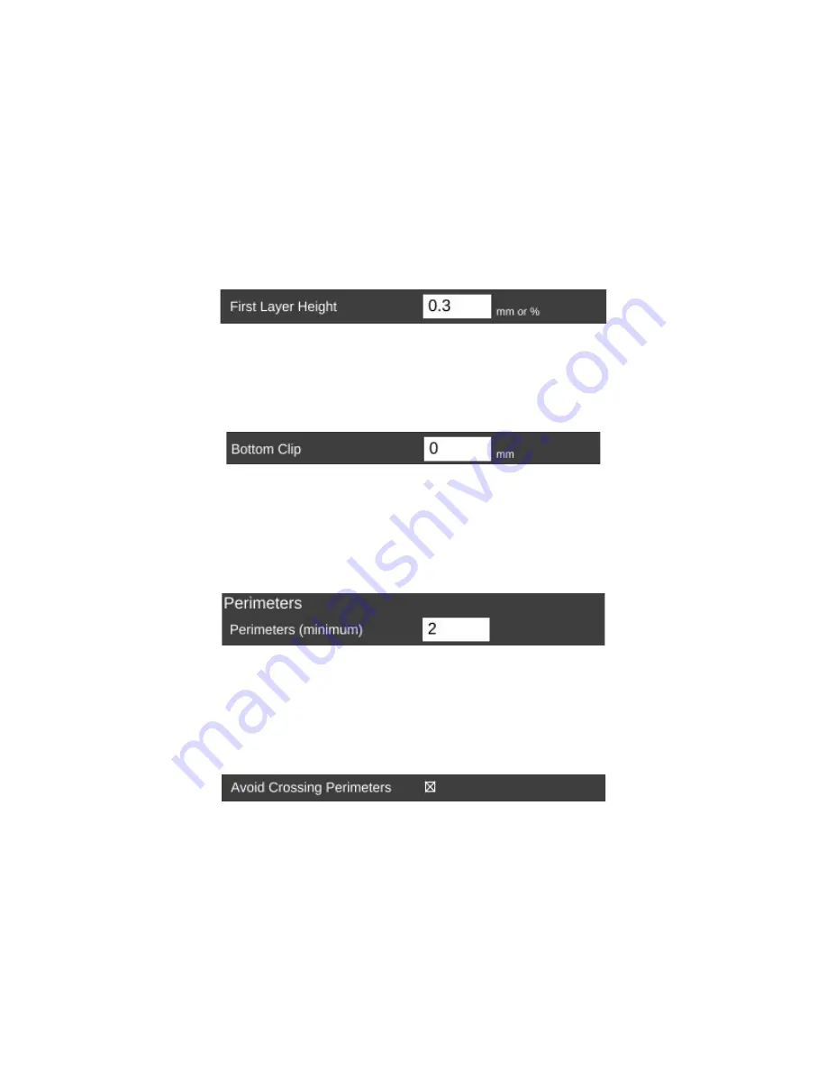
The
First Layer Height
parameter allows you to set the thickness of your first layer.
Having a thicker first layer will help provide a good base to build the rest of the part on as the
thicker (and thus wider extrusion) will help improve the adhesion to the bed. If your first layer
isn't any good, the part could eventually separate from the bed and ruin the print job.
Bottom Clip
allows you to tell the slicing engine that you'd like to “clip off” a specific
amount from the bottom of the model. For example, say you've got a 200mm tall model, but
you only want to print the top 50mm or so. You can enter 150 into the
Bottom Clip
field and
when the slicer generates the G-code for the print job, it will begin slicing 150mm up from the
bottom of the model.
Perimeters
dictate how thick the “skin” of your model is. 2 or 3 perimeters are good for
most parts, but if you want a really strong exterior wall, you can make the perimeter count as
high as you feel you need it. To get an idea of how thick the skin will be, you multiply the
perimeter count by the extrusion thickness (we'll get to that parameter in a bit). For example, if
you have a 0.5mm nozzle, chances are your extrusion thickness will be set to 0.5. 2 perimeters
will give you a skin thickness of 1mm.
When
Avoid Crossing Perimeters
is enabled, the nozzle path will not cross a part
perimeter during travel moves. This will help reduce the opportunity for stringing or oozing since
the nozzle tip is rarely over open air. For instance, if the tool path would normally cause the
nozzle to travel from one side of the part to the other, it would cross at least two perimeters and
may leave strings of material in its wake as it moves. If it is set to not cross perimeters, it will
cause the nozzle to trace a perimeter back to the nearest point where it can begin printing again
instead of jumping straight across to the new extrusion position.
72


