Ross Synergy 2 SD Installation Manual Download Page 167

Synergy Series Installation Guide (v18)

Basic Communications Setup • 7–11
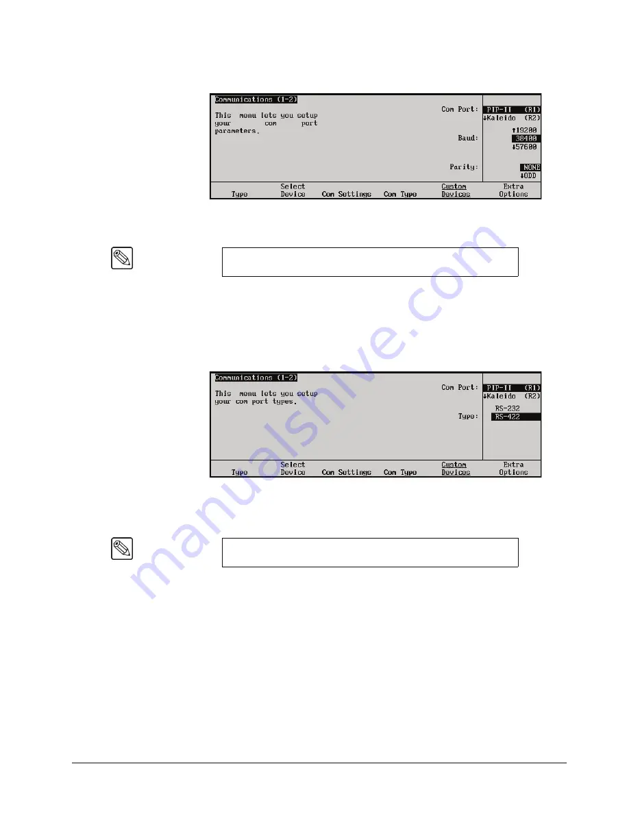
6. Press

 Com Settings 

to display the 

Com Settings Menu

.

Communications — Com Settings Menu

7. Set the communications protocols for the PIP-II device as follows:

Use  the 

Com Port 

knob


to select the PIP-II port you are setting the 

communications settings for.

Use  the 

Baud 

knob to select the baud rate for the PIP-II device.

Use  the 

Parity 

knob to select the parity for the PIP-II device.

8. Press 

Com Type 

to display the 

Com Type Menu

.

Communications — Com Type Menu

9. Select the type of serial communications that will be used to communicate with the 

PIP-II device as follows:

Use  the 

Com Port 

knob


to select the PIP-II device you want to set the 

communications type for.

Use  the 

Type

 knob to select the type of serial communications for the selected port.

10. Press 

Extra Options 

to display the 

Extra Options Menu

.

Note

Refer to your PIP-II device documentation for the specific Baud and 
Parity settings of your PIP-II device.

Note

Refer to your PIP-II device documentation for the specific 
communications type of your PIP-II device.

Summary of Contents for Synergy 2 SD

Page 1: ...Ross Video Limited Installation Guide Volume I Software Issue 18...

Page 2: ...of copyrighted software is prohibited Notice The material in this manual is furnished for informational use only It is subject to change without notice and should not be construed as commitment by Ros...

Page 3: ...he Product Manual Documentation Failure to heed this information may present a major risk of damage or injury to persons or equipment Warning The symbol with the word Warning within the equipment manu...

Page 4: ...uctor in the equipment s supply cord provides this protective earth To reduce the risk of electrical shock to the operator and service personnel this ground conductor must be connected to an earthed g...

Page 5: ...y approved A C wall plug certified for the country of use is required Alternatively other IEC 320 C 13 type power cords may be used provided that they meet the necessary safety certification requireme...

Page 6: ...ystem before PCB removal A Word About Static Discharge Throughout the many procedures in this guide please observe all static discharge precautions Notice This is a Class A product In domestic environ...

Page 7: ...be supplied free of charge while defective items undergo repair Return packing shipping and special handling costs are the responsibility of the customer Software upgrades for switchers may occur from...

Page 8: ...ral resources Ross Video encourages you to use the appropriate take back systems These systems will reuse or recycle most of the materials from your end of life equipment in an environmentally friendl...

Page 9: ...O Box 880 Ogdensburg New York USA 13669 0880 General Business Office Fax Technical Support After Hours Emergency E mail Technical Support E mail General Information Website 1 613 652 4886 1 613 652 4...

Page 10: ......

Page 11: ...Panel Top View 2 4 Synergy Control Panel Rear Connector Panel 2 6 Synergy Control Panel Power Connectors 2 7 Synergy Frame Overview 2 8 Synergy Frame Front View 2 8 Synergy Frame Rear Connector Panel...

Page 12: ...imated Logo Generator CDK 111A M Cabling 3 7 DSK 3 4 CDK 111A M Cabling 3 9 Power Up 3 11 Resetting the System 3 12 Full Reset 3 12 Software Reset 3 12 Preliminary Functional Check 3 14 Basic Troubles...

Page 13: ...eys 6 21 Basic Communications Setup 7 In This Chapter 7 1 Communications Menu Tree 7 2 Remote Port Expander BSS4 Setup 7 3 Remote Port Expander Communications Setup BSS4 7 3 Connecting Equipment to th...

Page 14: ...ls 9 12 Output Setup 9 15 MLE Tally Setup 9 15 MLE Aspect Ratio Setup 9 16 Clean Feed Setup 9 16 Fade to Black Setup 9 17 Ancillary Data 9 18 Trigger Field Setup 9 20 Standard GPI Setup 9 22 Standard...

Page 15: ...t Settings 10 18 Recall Factory Menu Tree 10 20 Recall Factory Procedure 10 20 When Configuration is Complete 10 24 Still Stores 11 In This Chapter 11 1 Supported Still Stores 11 2 Communications Conn...

Page 16: ...onnections 13 9 GPI Output Connections 13 10 Remote Control Connections 13 10 Communications Setup 13 11 Setting up BNCs for External DVEs 13 11 Setting Up Auto Keys 13 12 Setting Up Aux Bus Tallies 1...

Page 17: ...ers 17 Video Servers VDCP 18 Robotic Cameras 19 Monitor Walls 20 Audio Mixers 21 Appendix A Specifications 22 Appendix B Diagnostics 23 Appendix C Hardware Options 24 Appendix D Frame Modification 25...

Page 18: ...viii Contents Synergy Series Installation Guide v18...

Page 19: ...SD Series digital video production switchers You have purchased the power and versatility of a digital Multi Level Effects MLE switcher that is ready to take on all creative challenges in today s com...

Page 20: ...ll areas of the switcher Chapter 5 Using the Menu System provides an introduction to the Synergy switcher s menu system Chapter 6 BNC Configuration and Check provides instructions for configuring and...

Page 21: ...r connecting and setting up a Robotic Camera with your Synergy switcher Chapter 20 Monitor Walls provides instructions for connecting setting up and operating a Monitor Wall with your Synergy switcher...

Page 22: ...also provided for your reference If at any time you have a question pertaining to the installation of your Ross Synergy switcher please contact us at the numbers listed in the front of this guide Our...

Page 23: ...xt For example The Aux Bus Setup Menu allows you to Soft key labels on the integral display are indicated in bold faced text using a sans serif font They are not indicated by the function key below th...

Page 24: ...a Synergy SD Switcher via RS 422 serial control This type of connection allows you to run the DVE using custom control buttons and by using the DVE SEND feature in the Transition group You can also lo...

Page 25: ...to Analog DA Distribution Amplifier DDR Digital Disk Recorder DSK Downstream Keyer DVE Digital Video Effects DVR Digital Video Recorder ID Identification MLE Multi level Effects PGM Program Bus PST P...

Page 26: ...e added option to use those converters for other purposes as they gradually convert to the digital domain Large Input Matrix The Synergy SD frame can accept up to 64 video inputs in groups of eight in...

Page 27: ...d to provide advanced operational features Preview Overlay This powerful option presents VTR time code a count up down timer source ID safe title and more Displays are individually selectable on the p...

Page 28: ...e Tease feature can be installed in every MLE in the switcher allowing you to squeeze or zoom any key or full screen image Each MLE features five comprehensive matte generators two of which incorporat...

Page 29: ...or a selected color To simplify fast paced live operation the advanced menu system controls can be disabled This allows you to quickly set up high quality keys using a minimum number of dedicated knob...

Page 30: ...tion switchers Clean Feed The Clean Feed feature provides a second program output that is derived from a different location than the standard program output Typical applications are Bilingual and live...

Page 31: ...use Clean Feed to output signals in two aspect ratios Key 1 outputs a signal in 4x3 aspect ratio standard definition Key 2 uses the Aspectizer option to output a signal in 16x9 anamorphic aspect rati...

Page 32: ...e but the MLE is not on air Every auto transition rate is constantly visible including the main transition rates the dedicated keyer rates and the fade to black rate The last memory number recalled pe...

Page 33: ...system reference Signal sources of other video formats must be converted to serial digital Ross Video chose to do this conversion externally to ensure that the very latest conversion technology and m...

Page 34: ...The Preview Overlay option makes it possible to present various types of useful information on one of the two main preview outputs This information is color coded and can be positioned and displayed...

Page 35: ...output around any active box mask The AREA buttons in the effects control area determine which box mask is currently being viewed The Preview Overlay option is a circuit card that installs on the Fram...

Page 36: ...o eight DVEs One Squeeze Tease 2D option can perform the following digital video effects using only one keyer Squeeze crop and reposition an image with variable colored borders Squeeze crop and reposi...

Page 37: ...er hard or glowing edges The option also enhances self keys chroma keys and preset pattern keys You can move the border to any position on screen even above the key Borders are flown in real time with...

Page 38: ...uttons Synergy 2 SD each panel includes 17 source buttons plus SHIFT and a button for MLE 1 Synergy 3 SD each panel includes 30 source buttons plus SHIFT and buttons for MLE 1 and MLE 2 Synergy 4 SD e...

Page 39: ...ommand to the device selected on the PST bus The operator then manually transitions the source to air by moving the fader or by pressing the CUT AUTO TRANS or the device s crosspoint on the PGM bus Wh...

Page 40: ...control for enhanced audio follow video from the Synergy SD Switcher over large audio mixers making an integrated A V production possible This protocol supports the associating of any audio input with...

Page 41: ...nto the Custom Control buttons Audio Server Control The Audio Server Control Option controls up to eight audio servers such as the Digicart by 360 Systems directly from the Synergy control panel Inter...

Page 42: ...nput or MLE program output The Extended Tallies option provides an additional 36 tallies bringing the total number to 72 These additional tallies are equally configurable They can be added for red gre...

Page 43: ...in the frame s top slot Spare Parts Kit A Spare Parts Kit is available which provides switcher parts according to the following criteria the part comes into frequent contact with the user the part can...

Page 44: ...ss personnel During business hours eastern standard time technical support personnel are available by telephone any time After hours and on weekends a direct emergency technical support phone line is...

Page 45: ...l Panel Overview Synergy Frame Overview Installation at a Glance Hardware Installation Installing the Control Panel Installing Remote Aux Panels Installing the Electronics Frame Installing the Frame P...

Page 46: ...charge can cause serious damage to sensitive semiconductor devices Avoid handling the switcher circuit boards in high static environments such as carpeted areas and when synthetic fiber clothing is wo...

Page 47: ...ptions and accessories Once the boxes are unpacked check the contents against the packing list to ensure that all items are included If any items are missing or damaged contact your sales representati...

Page 48: ...STORE MLE RATE KEY RATE MLE 1 MEMORY SYSTEM RECALL 1 2 3 4 5 6 7 8 9 BANK 0 ENTER KEYS ONLY EFF DISS STORE MLE RATE KEY RATE PST BLACK DISS CUT WIPE DVE SEND AUTO TRANS ROLL VTR DSK1 DSK2 BKGD TRANS...

Page 49: ...gy 3 Control Panel comes standard with three MLEs and 24 inputs Synergy 3 Control Panel with USB Removable Media Drive Option Synergy 2 Control Panel The Synergy 2 control panel comes standard with tw...

Page 50: ...ting with remote peripheral devices such as VTRs disk recorders video servers or other serial controlled devices The ports can be configured as RS 422 or RS 232 through the menu system 3 Tally Connect...

Page 51: ...tors will differ depending upon the size of your specific Synergy switcher Synergy Series Control Panel Rear View Power Section Please note that each AC connector includes a power lock to retain the p...

Page 52: ...w The following figure illustrates the front of the frame with the door removed Synergy Series Frame Front View 1 Power Controls and Indicators 2 Power Supply Tray Handle 3 Frame CPU Board Aux Bus Boa...

Page 53: ...the primary power supply has failed or is not connected properly SECONDARY FAIL indicates that the secondary redundant power supply has failed or is not connected properly FAN FAIL indicates that one...

Page 54: ...ided for 8 input digital video crosspoint boards for a maximum of 64 digital inputs Each crosspoint board is identical and any crosspoint board can be installed in any slot Configuration of each input...

Page 55: ...ection 4 Aux Output Section 5 Special Output Section 6 DVE 1 Connector 7 DVE 2 Connector 8 Peripheral 1 Connector A 9 Peripheral 1 Connector B 10 Peripheral 2 Connector A 11 Peripheral 2 Connector B 1...

Page 56: ...electronically place that input anywhere on the control panel s MLE bus row All input configuration is performed through the menu system 3 Main Output Section Ten BNCs are provided for the switcher s...

Page 57: ...must be installed The overlay is switched from the control panel s PREVIEW OVERLAY group When the PV output switches the OVL output tracks in sync SPARE provides a spare output for future use The out...

Page 58: ...ntrol requirements such as control panel networking 10 Peripheral 2 Connector A One 9 pin D Type RS 422 connector labeled PERIPHERAL 2 is provided for connection to a secondary peripheral device The c...

Page 59: ...ommon ground 12 GPI outputs and 12 GPI inputs 14 Control Panel Connector One 8 pin shielded Telco connector labeled PANEL is provided for communications between the chassis and the control panel Impor...

Page 60: ...utput monitors as required for your installation Make connections to external equipment The ways of connecting such sources will depend on personal preference as well as on the combination of options...

Page 61: ...install the control panel tub itself and some push button inserts Each tub is designed to be set into a desk or console cutout Use the following procedure to install the control panel 1 Measure your...

Page 62: ...n two inches 5 0 cm of the console front as shown in the diagrams above This placement is designed for the convenience of the operator Distance from Cutout to Console Front Recommended 2 0 5 0 cm 50 2...

Page 63: ...stall them from the top making sure that they do not protrude through the bottom of the tub 5 Normally fasteners are not required to hold the control panel in place However if your installation requir...

Page 64: ...neutral or return side GREEN ground or earth Protective Earth The safe operation of this product requires that a protective earth connection be provided This protective earth is provided by the ground...

Page 65: ...or is provided for 5 VDC panel power 2 GPI Port One 9 pin D GPI connector is provided for special GPI triggers that allow a camera operator to manually override the Aux panel selection Refer to the se...

Page 66: ...ettable jumpers in the Aux panels Assignable Aux panels are configured using the control panel s menu system A special programming mode allows you to assign rights for each of the 12 available Aux out...

Page 67: ...rs on the sides of the boards allow easy installation and removal Installing the Frame Door If you have the room in your rack leave a 1RU space above the frame to prevent the equipment directly above...

Page 68: ...left of the power supply module loosen the two mounting screws that secure the power supply s safety bracket in place 5 Place the bracket behind the fold over to the left of the power supply s frame...

Page 69: ...tes the procedure to install frame power Please note that each AC connector includes a power lock which is designed to retain the power cable connector Caution In some countries it may be necessary to...

Page 70: ...th the power switches in the OFF position To avoid electrical shock disconnect all A C power cords from the rear of the panel before removal of this barrier Service barriers within this product are in...

Page 71: ...is reserved for future use Please leave the switch in the default Off position as labeled on the switch 3 Configuration Switch 2 This switch is reserved for future use Please leave the switch in the d...

Page 72: ...r is not installed The red POWER FAIL indicator will not light Frame Jumpers and Switches For all switchers the following figure illustrates the location of jumpers and switches on the front edge of t...

Page 73: ...leave it in the default Down position 7 JP7 Reserved Jumper JP7 is reserved for future use Please leave it in the default Down position 8 JP8 Reserved Jumper JP8 is reserved for future use Please lea...

Page 74: ...failure on the POWER FAIL indicator LEDs In addition the control panel menu displays the Splash Screen On a Synergy 4 switcher when frame power is restored the power failure status indicator clears a...

Page 75: ...lure all MLE setups return exactly as they were immediately before the power failure Please note A loss of control panel power only has no effect on the frame because the frame stores the current vide...

Page 76: ...l 1 Navigate to the Installed Options Menu as follows Press HOME B MORE B Setup B Installed Options 2 Press Panel Boards to display the Panel Boards Menu Installed Options Panel Boards Menu 3 Locate t...

Page 77: ...a safe place It is recommended that you place the following information on the label Synergy SD Switcher Model 2 3 or 4 Software Version vXX xx Backup Today s Date This completes the procedure for sa...

Page 78: ...ade Disk 1 in the drive When prompted remove Disk 1 insert Disk 2 press Continue and wait for the upgrade process to complete The software is complete when the menu buttons flash in marquee fashion 8...

Page 79: ...ion 8 Power off the frame 9 Power off the control panel 10 Move the jumper on JP11 on the Frame CPU Board to the Down position 11 Power on the frame and the control panel in any order desired This com...

Page 80: ...If not refer to the section Software Upgrade on page 2 34 2 Locate the backup storage device that you made in the section System Backup on page 2 33 3 Naivgate to the Disk Menu as follows Press HOME B...

Page 81: ...e Software Options Menu lists your Synergy frame s serial number at the top This number is present at the top of all options menus The main area also provides two columns of information Column 1 lists...

Page 82: ...umbers are unique and pertain to your switcher only The serial numbers cannot be exchanged or entered on another switcher Panel Boards Menu The Main Area of the Panel Boards Menu provides three column...

Page 83: ...Boards Menu 3 Use the middle knob to scroll the list Note that the menu is provided for information only no action can be taken This completes the procedure to view the frame boards you have installe...

Page 84: ...led Squeeze Tease Dual Border Generator The status for each input slot reflects whether or not the optional Input Carrier Board is installed Each Input Carrier Board has sockets provided for up to fou...

Page 85: ...o the Installed Options Menu 1 2 as follows Press HOME B MORE B Setup B Installed Options 2 Press Software Options to display the Software Options Menu 3 Press Add Option to display the Enter Serial N...

Page 86: ...vigate to the Installed Options Menu 2 2 as follows Press HOME B MORE B Setup B Installed Options B Software OptionsB MORE Installed Options Menu 2 2 2 Insert a storage device into the Synergy switche...

Page 87: ...lled Options B MORE 2 Insert the storage device containing the Software Option Codes backup that you created in the section Storing Option Codes on page 2 42 You must wait 5 seconds after inserting th...

Page 88: ...2 44 Installation Synergy Series Installation Guide v18...

Page 89: ...r connections A preliminary functional check procedure is also provided The following topics are discussed Cabling Control Cable Installation Remote Aux Panel Cabling Reference Signal Connection Monit...

Page 90: ...1 12 13 14 15 16 17 18 19 20 21 22 23 24 25 26 27 28 29 30 31 32 33 34 35 36 37 38 39 40 41 42 43 44 53 54 55 56 61 62 63 64 PV EXP 4 EXP 2 AUX 11 OVL SPARE EXP 3 EXP 1 AUX 12 PV CLEAN PGM AUX 6 AUX 4...

Page 91: ...opics are discussed Remote Aux Panel Cabling Old Version Panels Remote Aux Panel Cabling New Version Panels Aux Panel Cabling Notes applies to all panel versions Depending upon the type of Remote Aux...

Page 92: ...the correct 6 pin shielded Telco cable with 6 pin connectors at each end Because of their small size all Telco connectors look quite similar 2 Connect a 6 pin shielded Telco cable of the supplied or...

Page 93: ...ional Aux panels in the AUX 1 daisy chain up to the maximum of 8 panels per chain 5 Repeat steps 1 through 3 for the switcher control panel s AUX 2 and AUX 3 connectors This completes the procedure to...

Page 94: ...rovide the typically required color bar input all in one signal Monitor Connection Connect either the PGM 1 or PGM 2 BNC output on the rear of the frame to your serial digital program monitor Please n...

Page 95: ...the DCP 111 panel to BNC 2 ALG CDK 111A M Cabling Diagram Important Before turning on the power please ensure that the rotary switch on the front edge of the CDK 111A M card as indicated on the follo...

Page 96: ...ion Guide v18 ALG CDK 111A M Card Edge Refer to the section Animated Logo Generator Mode in the CDK 111A M Owner s Guide for complete instructions on installing configuring and operating your CDK 111A...

Page 97: ...to BNC 3 and BNC 4 on the external DSK Depending on your site layout add extension cables from either end if necessary Serial Interface Cable 4 Connect the designated untimed Aux Buses for key video...

Page 98: ...the section DSK 3 4 CDK 111A M Communications Setup on page 7 19 for instructions on installing and seating cards Important Before turning on the power please ensure that the rotary switch on the fron...

Page 99: ...el tub on the right hand side Open the panel tub and turn on the Primary and if installed the Redundant power switches 3 Close the control panel tub 4 Frame power switches are located on the bottom ri...

Page 100: ...to the section Jumpers and Switches on page 2 26 for additional information on the frame and control panel RESET switches Software Reset The software reset function can be performed from either the Gl...

Page 101: ...To reset MLE 1 in MLE 1 s Memory group simultaneously press STORE and RECALL To reset MLE 2 in MLE 2 s Memory group simultaneously press STORE and RECALL To reset MLE 3 in MLE 3 s Memory group simulta...

Page 102: ...et state 2 Ensure that your reference video is connected to input 1 3 Check the status of the control panel In a reset or default condition the following buttons and indicators will be lit The first c...

Page 103: ...e that BLACK is selected on the PGM Bus Select COLOR BKGD 1 on the PST Preset Bus Color Background 1 is factory preset to red Color Background 2 is factory preset to blue 5 Ensure that DISS is selecte...

Page 104: ...e reference signal is invalid or not present If you have the USB Removable Media Drive option installed you may receive the error message USB Upgrade Failed after restoring power to the control panel...

Page 105: ...tcher You will complete input and output worksheets connect inputs and alpha signals install all pushbutton inserts and connect your switcher outputs The following topics are discussed Input Worksheet...

Page 106: ...during the initial cabling procedure Connect your Key signals alphas to your highest available input number and then continue backwards in sequence For example Synergy 2 assuming 16 standard inputs s...

Page 107: ...E VTR Reference Alpha Router Still Store Robotic Cam Video Fill in the input s tally number If the input is an alpha choose between Shaped S or Unshaped U Keying mode Luminance Filter On or Off If the...

Page 108: ...Actual Source Remote Port Device Address Input Name Input Type Tally Number Alpha Type Auto Key Audio Channel Button Sample 1 VTR 1 Remote 1 VTR Blue VTR 12 5 Sample 2 CG Alpha Remote 2 CG Alpha Alpha...

Page 109: ...Installation 4 5 32 33 34 35 36 37 38 39 40 41 42 43 44 45 46 47 48 49 50 51 52 53 54 55 56 57 58 59 60 61 62 63 64 BNC Input Worksheet BNC Actual Source Remote Port Device Address Input Name Input Ty...

Page 110: ...located in the Inputs section on the rear of the frame as shown below Each input is identified in the label array to the right of the connectors Input BNC Connections Operating Tip Use cabling techniq...

Page 111: ...tion Synergy 2 To view inputs 2 through 14 press buttons 2 through 14 respectively Buttons 1 15 16 and 17 are already mapped as indicated above To view inputs 15 through 30 press SHIFT buttons 1 throu...

Page 112: ...33 through 64 press SHIFT buttons 1 through 32 respectively Button 35 is mapped to SHIFT on the shifted row Operating Tip You can also double press the SHIFT button to have the MLE remain in the shif...

Page 113: ...ased to consider adding it to the standard film There are four typical ways of labeling a pushbutton Use our standard inserts Ask us to make custom inserts Make your own inserts using transparency mat...

Page 114: ...the following diagram during this procedure Aux Panel Pushbutton Inserts Operating Tip If you have trouble removing a control panel button use a pair of wide tipped pliers 1 2 inch with masking tape w...

Page 115: ...utton assembly 3 Remove the lens cap by gently prying the lens cap out of the button assembly 4 Place the designation insert in the lens cap 5 Replace the paper background behind the designation film...

Page 116: ...switcher Complete the auxiliary output worksheet on page 4 12 Or to avoid marking up this guide use the worksheet provided in Appendix E Switcher Installation Worksheets to make extra copies Primary O...

Page 117: ...omplete the special output worksheet on page 4 14 Or to avoid marking up this guide use the worksheet provided in Appendix E Switcher Installation Worksheets to make extra copies Auxiliary Output Work...

Page 118: ...view overlay must be installed for a signal to be present SPARE The output is currently not implemented EXP 1 The output is currently not implemented EXP 2 The output is currently not implemented EXP...

Page 119: ...y Output Worksheet connect the following primary outputs to the desired external destinations such as program monitors preview monitors transmission routing switchers etc Remember that the MAIN PGM ou...

Page 120: ...y be a monitor however if the destination is a VTR or a routing switcher ensure that you can monitor the input signal to the specific device Primary Output Verification Output to Verify Verification M...

Page 121: ...press ASSIGN 8 then switch between inputs on AUX Bus AUX 9 In the AUX BUS ASSIGN group press ASSIGN 9 then switch between inputs on AUX Bus AUX 10 In the AUX BUS ASSIGN group press ASSIGN 10 then swit...

Page 122: ...4 18 Preliminary Video Installation Synergy Series Installation Guide v18...

Page 123: ...1 Using the Menu System In This Chapter This chapter introduces the menu system of the Synergy SD Switcher The following topics are discussed About the System Control Display Menu System Basics Positi...

Page 124: ...tically depending on certain functions that you select on the control panel In this way additional adjustment parameters are instantly available to you as soon as you press a control panel button You...

Page 125: ...me On the Main Menu accessible by pressing HOME note that the software version is displayed below the menu name When parentheses are shown the MORE button lights Press MORE to display the second menu...

Page 126: ...e three Positioner Icons appear in this area you can adjust the selected function or parameter either with the Scroll Knobs or with the Positioner Refer to the section Positioner Icons on page 5 5 for...

Page 127: ...vel While the Soft Keys move you vertically through the menu system MORE moves you horizontally Press MORE to display the second menu in the series or to return from the second menu to the first For e...

Page 128: ...Operation Guide for additional information on the Positioner itself and the three Positioner Icons Adjusting the Display Use the following procedure to adjust the brightness or contrast of the large...

Page 129: ...sted function Use the following procedure to access the Help Menu 1 Navigate to the Help Menu as follows Press HOME B Help Help Menu 2 Use the middle knob to highlight the switcher function that you w...

Page 130: ...d to alert the operator when an illegal function is attempted When the illegal button is pressed the Pop up Help Menu appears providing a brief explanation of why the operation cannot be performed A s...

Page 131: ...3 Simultaneously press the FADE RATE and ALL buttons in the STORE Area of the Global Memory System Group The light on the drive will come on the current menu freezes and a popup message is displayed...

Page 132: ...5 10 Using the Menu System Synergy Series Installation Guide v18...

Page 133: ...is used by the switcher to provide the desired names sources Key and fill associations and overall switcher functionality The following topics are discussed Installation Enable Jumper Setting BNC Conf...

Page 134: ...on Enable Jumper JP10 on the front edge of the Frame CPU Board is in the Down position This position allows all installation settings to be changed without restriction Refer to the section Frame Jumpe...

Page 135: ...y Effects Setup Menu Installation Menu 1 Display Panel Diagnostics Installation Personality BNC Aux Bus Communications Output GPI I O DSK Installed Options Frame Diagnostics Main Menu 2 MORE Setup Cli...

Page 136: ...sing the BNC Names Menu This allows you to use actual input names throughout the menus Additionally the names that you choose will appear on the Preview Overlay output provided that the Preview Overla...

Page 137: ...yboard in the Synergy Series Operation Guide for details 4 There are two ways to begin editing the BNC name You can begin by choosing a preset name a prefix from a list of typical BNC names To start i...

Page 138: ...urrent position If a letter is in the active position it will be deleted Press Prev Letter to move the highlight one space to the left Press Next Letter to move the highlight one space to the right 7...

Page 139: ...duction of the Synergy Series Operation Guide for details 3 Press Default softkey to change the BNC name to the default format 4 Press Accept New Name This completes the procedure to restore the defau...

Page 140: ...background Large Select this option to use a large font that permits only 2 characters per line Large Invert Select this option to use a large font that permits only 2 characters per line and draws li...

Page 141: ...cal BNC connectors with input types These associations play important roles throughout the system particularly with regard to filtering subsequent BNC setup menus based on specific input types The Mai...

Page 142: ...VTR to the Synergy switcher You will need the Video Server Control or Audio Server Control Software Options depending on the device you are connecting Reference Select this option when a reference vid...

Page 143: ...on Use this option unless the input is an alpha reference or a device listed above is connected to that BNC and controlled by the Synergy switcher Refer to the chapter Basic Communications Setup on pa...

Page 144: ...have will depend on the number of upper MLEs you have on your switcher MLE PST Select this option to tally the selected BNC or MLE when it is selected on the PST bus of a particular upper MLE The numb...

Page 145: ...Use the Type knob to select Alpha Use the Asp Ratio knob to select the native aspect ratio of the input Key alpha video signal 4 Press Alpha to display the Alpha Setup Menu BNC Alpha Setup Menu 5 Def...

Page 146: ...DVE 1 Alpha This association completely simplifies the Keying process on the switcher When you punch up a key source on the Key bus its alpha and fill are automatically selected Use the following proc...

Page 147: ...at you want to assign a BNC input to By default BNC inputs are mapped to crosspoint buttons on a one to one assignment For example BNC 1 will be assigned to crosspoint button 1 BNC 2 will be assigned...

Page 148: ...When active the Bus Hold function allows you to retain the current crosspoint on a bus during a memory recall Refer to the section Bus Hold Function on page 6 18 for more information on using this fun...

Page 149: ...you may wish to assign Color Background 2 as the shifted function of Color Background 1 For convenience you can place alphas as the shifted button of the associated fill However if you are short on i...

Page 150: ...ing Up N S Disable The N S Disable Menu gives you the option to disable the non sync LEDs for all or individual BNCs When a BNC has the N S Disable set to ON the non sync indicator on the panel will n...

Page 151: ...ing and asks you to confirm the changes This warning occurs only when the following conditions are met The Installation Enable Jumper JP10 on the front edge of the Frame CPU Board is in the Down posit...

Page 152: ...3 Ensure that the program monitor is connected to the MAIN PGM output connector on the rear of the chassis 4 Ensure that each source device connected to the switcher is putting out a signal 5 Using y...

Page 153: ...ections 3 In the MLE s Key 1 Group Press AUTO SELECT to select a linear key type The KEY MEM button will automatically light Press CUT to take the key to air The CUT button lights momentarily and the...

Page 154: ...me and BNC number are shown The correct key alpha source name and BNC number are shown The correct key attributes are shown e g shaped 6 If the key alpha and fill sources are incorrectly paired or imp...

Page 155: ...own in the Scroll Area of the Auto Key Setup Menu By default the labels in the Scroll Area both indicate Locked for the selected Key This shows that the factory default settings for the selected alpha...

Page 156: ...6 24 BNC Configuration and Check Synergy Series Installation Guide v18...

Page 157: ...chapter provides instructions for setting up communications parameters with peripheral equipment The following topics are discussed Communications Menu Tree Remote Port Expander BSS4 Setup Custom Dev...

Page 158: ...ation Personality BNC Aux Bus Communications Output GPI I O DSK Installed Options Frame Diagnostics Main Menu 2 MORE Setup Clips Aux Bus Logo MORE Communications Menu 1 Communications Menu 2 Com Setti...

Page 159: ...S4 to the Synergy switcher Remote Port Expander Communications Setup BSS4 Use the following procedure to configure the BSS4 Remote Port Expander 1 Navigate to the Communications Menu 1 2 as follows Pr...

Page 160: ...the Baud knob to select 115200 as the baud rate for the BSS4 The Parity knob is fixed at NONE 8 Press Com Type to display the Communications Type Menu Communications Communications Type Menu 9 Select...

Page 161: ...ng you that the BSS4 Remote Port Expander has been successfully programmed BSS4 Successful Program BSS4 Screen 16 Move the SET UP SWITCH on the BSS4 to NORM 17 Disconnect the BSS4 Power Supply from th...

Page 162: ...Peripheral Devices on page 7 7 for more information on programming the BSS4 Devices that use a Parity other than the current rate that the port on the BSS4 is set for will require programming of the B...

Page 163: ...ts on the Switcher Programming the BSS4 for Peripheral Devices If you set up a device that uses a baud rate or parity that is different than what the remote port on the BSS4 is set to you will have to...

Page 164: ...4 Successful Program BSS4 Screen 7 Move the SET UP SWITCH on the BSS4 to NORM 8 Disconnect the BSS4 Power Supply from the BSS4 to cycle the power Off 9 Reconnect the BSS4 Power Supply to the BSS4 to c...

Page 165: ...Device Setup procedure allows you to set up communications parameters with custom external devices Note The Custom Device Setup is an advanced feature requiring technical knowledge of serial protocol...

Page 166: ...procedure to configure a Synergy switcher communication port for a Peripheral Interface II Protocol device 1 Navigate to the Communications Menu 1 2 as follows Press HOME B MORE B Setup B Installation...

Page 167: ...evice 8 Press Com Type to display the Com Type Menu Communications Com Type Menu 9 Select the type of serial communications that will be used to communicate with the PIP II device as follows Use the C...

Page 168: ...hether they respond to the Query Command or not Silent Select this option to not send the Query Command The switcher will be able to control all devices connected to your PIP II device 12 Press HOME t...

Page 169: ...dure to set up communication parameters with tally system interface equipment using industry standard protocol Use the following procedure to configure the Contribution Serial Tally Protocol 1 Navigat...

Page 170: ...cted com port Refer to the section Look Ahead Serial Tallies Protocol Setup on page 7 16 for more details 6 Press Com Settings to display the Com Settings Menu Communications Com Settings Menu 7 Set t...

Page 171: ...the tally interface equipment 12 Assign a data transfer size to the tally interface as follows Communications Extra Options Data Transfer Menu Use the Com Port knob to select the tally interface you a...

Page 172: ...out making any changes The system returns to the previously stored settings This completes the procedures for setup of the Contribution Serial Tally Protocol option If you require further information...

Page 173: ...ystem communications port as follows Use the Com Port knob to select the communications port you want to assign a specific tally interface to Use the Device knob to select the type of tally interface...

Page 174: ...select between 0 and 120 fields for the delay duration 8 Press HOME to display the Installation Change Confirmation Screen 9 Accept or reject the changes you have made as follows Press Confirm to acc...

Page 175: ...111A M Cabling on page 3 9 and the section DSK 3 4 CDK 111A M Cabling on page 3 9 2 Navigate to the Communications Menu 1 2 as follows Press HOME B MORE B Setup B Installation B Communications 3 Pres...

Page 176: ...m Port knob to select the DSK you are setting the communications settings for Use the Baud knob to select 19200 as the baud rate for the CDK 111 Use the Parity knob to select ODD 9 Press Com Type to d...

Page 177: ...ing topics are discussed Custom Control Banks Menu Tree Custom Controls Menu Tree Custom Controls Custom Control Banks Programming Control Panel Functions Relative Custom Controls Programming Special...

Page 178: ...Help Preview Overlay Effects Setup Menu Installation Menu 1 Display Panel Diagnostics Installation Personality BNC Aux Bus Communications Output GPI I O DSK Installed Options Frame Diagnostics Main M...

Page 179: ...sert Robotic PIP II Menu Camera Menu Insert Monitor Wall Menu Insert Audio Server Menu Edit only shows up as a soft key if the custom control button currently selected in the System Control Group has...

Page 180: ...Group Synergy 2 Panel 2003 Edition Buttons are numbered to simplify the programming procedure The numbering is 1 to 17 in ascending order from left to right Synergy 3 The following figure illustrates...

Page 181: ...mmed to perform a specific transport command such as play cue and rewind Commands apply to serial controlled devices such as VTRs Video Servers and Audio Servers The VTR Remote Control Video Sever Con...

Page 182: ...Controls for more information on Robotic Camera Custom Controls Monitor Wall Functions A custom control button can be programmed to change input channels modify dynamic text and load a specific layou...

Page 183: ...place the bank buttons themselves Each bank stores a separate set of custom controls Custom Control Bank Setup Use the following procedure to set up Custom Control Banks 1 Navigate to the Custom Contr...

Page 184: ...om Control Bank Names Menu provides an array of letters and numbers The reverse video highlight indicates the selected character the position of which is controlled by the two upper scroll knobs In th...

Page 185: ...s in the active position it will be deleted Press Prev Letter to move the highlight one space to the left Press Next Letter to move the highlight one space to the right To return the currently modifie...

Page 186: ...ics to display Custom Control Bank Names Customizing Mnemonic Displays Banks The Custom Control Bank Names Menu allows you to adjust how bank names will appear in their associated mnemonic displays In...

Page 187: ...characters per line Small Invert Select this option to permit up to 6 characters per line and draw light text on a dark background Medium Select this option to permit up to 4 characters per line Mediu...

Page 188: ...nk You can choose from the following Standard Select this option to apply the color as defined in the Personality Menu Green Select this option to apply a green background to the display Yellow Select...

Page 189: ...sh to program You can also press the button directly on the panel 3 Press Start Recording to display the Recording Menu Custom Controls Recording Menu Operating Tip If you are programming long or loop...

Page 190: ...for more information DVE Functions Refer to the section External DVE Custom Controls on page 13 37 for more information Time Clock Functions Refer to the section Time Clock Functions on page 8 19 for...

Page 191: ...feature does not recognize analog knob adjustments or Fader movement Macros are restricted to button presses and functions on the Insert Special Menus only You can stop a custom control sequence macr...

Page 192: ...nto MLE 3 Configuration 1 we can recall that Relative Custom Control with more or fewer MLEs If we have MLE 1 re entered into MLE 2 and MLE 2 re entered into MLE 3 Configuration 3 the Relative Custom...

Page 193: ...l button that you wish to program You can also press the button directly on the panel 4 Press Start Relative Recording to display the Recording Menu Custom Controls Recording Menu 5 With the recording...

Page 194: ...stom Controls Menu You will notice an at symbol next to the custom control you just recorded indicating that this relative custom control contains information This completes the procedure for recordin...

Page 195: ...with special Time Clock functions 1 Navigate to the Custom Controls Menu as follows Press HOME B Custom Controls Custom Controls Menu 2 Select the custom control button you want to record to as follow...

Page 196: ...custom control button to finish recording to the selected custom control The custom control button will stop flashing Note The middle Reset Time knob only applies to the insert Reset command No value...

Page 197: ...ational convenience and efficiency These functions include Reset GPI Trigger GPI Automation Go To Menu Transition Keys Safe Title Roll VTR Mode Custom Control Holds Custom Control Pauses Reset GPI Use...

Page 198: ...tton to finish recording to the selected custom control The custom control button will stop flashing Once your custom control buttons have been programmed be sure to properly name them Refer to the se...

Page 199: ...sert Special B Special Insert Special Special Menu 4 Assign the trigger GPI to a GPI output as follows Use the top knob to select Trigger GPI Use the GPI Output knob to select the GPI output port you...

Page 200: ...e the Automation function to create custom controls that accept commands from an external automation system Use the following procedure to create an Automation custom control macro 1 Navigate to the C...

Page 201: ...e next step to complete the procedure 7 Press UP ONE to display the Recording Menu 8 Press Finish Recording or the flashing custom control button to finish recording to the selected custom control The...

Page 202: ...al Menu as follows Press Start Recording B Insert Special B Special Insert Special Special Menu 4 Assign a menu to display to the selected custom control macro as follows Use the top knob to select Go...

Page 203: ...play the Insert Special Menu 1 2 6 Insert additional commands if needed When you have finished inserting commands proceed to the next step to complete the procedure 7 Press UP ONE to display the Recor...

Page 204: ...ion the Keys for You can select between the following MLE 1 Select this option to transition the Keys on MLE 1 MLE 2 Select this option to transition the Keys on MLE 2 MLE 3 Select this option to tran...

Page 205: ...to the next step to complete the procedure 7 Press UP ONE to display the Recording Menu 8 Press Finish Recording or the flashing custom control button to finish recording to the selected custom contr...

Page 206: ...lled as follows Use the top knob to select Safe Title Use the Safe ID knob to select the stored Safe Title set up that you want to recall when you run the custom control 5 Press Insert to enter the sa...

Page 207: ...AUTO TRANS the device rolls and goes to air after the preroll interval has elapsed During preroll moving the fader pressing CUT or double pressing the crosspoint on the PGM bus will override the prero...

Page 208: ...Special Insert Special Special Menu 4 Change the Roll VTR Mode as follows Use the top knob to select Roll VTR Mode Use the Roll VTR Mode to select a Roll VTR Mode You can select between the following...

Page 209: ...for details Custom Control Holds Use the Custom Control Hold feature to place holds within a custom control sequence When entered these holds specify a point to stop and wait for a user button press...

Page 210: ...ssage displayed on the Main Menu or the Custom Control Menu when a custom control hold is being performed Main Menu Custom Control Held 1 Time Popup Select this option to have a pop up appear on any m...

Page 211: ...rol macro to Any recorded custom control can be edited Refer to the section Editing Custom Control Macros on page 8 47 for details Custom Control Pauses Use the Custom Control Pauses feature to place...

Page 212: ...Recording or the flashing custom control button to finish recording to the selected custom control The custom control button will stop flashing Once your custom control buttons have been programmed be...

Page 213: ...he Button knob to select the custom control button that you want to record a custom control macro to You can also press the desired button directly on the control panel Remember that buttons marked wi...

Page 214: ...mand into your custom control macro 6 Press UP ONE to return to the Custom Controls Recording Menu 7 Press Finish Recording or the flashing custom control button to finish recording to the selected cu...

Page 215: ...ontrol bank that you want to record the custom control on Use the Button knob to select the custom control button that you wish to program You can also press the button directly on the panel 3 Press S...

Page 216: ...matte generator values fader positions on air status key active status and key over priorities If a re entry selection is invalid on the destination MLE BLACK is automatically selected when the copy...

Page 217: ...d to an MLE the MLEs do not have a PST BLACK button In each of these situations the Synergy switcher will perform the copy and electronically set up the desired effect even though it is not physically...

Page 218: ...Controls Menu as follows Press HOME B Custom Controls Custom Controls Menu 2 Select the custom control button you want to set the name for Use the Bank knob to select the custom control bank with the...

Page 219: ...e for details 5 Assign a Preset Name to the custom control as follows Press Preset Names to display the Preset Names Menu Preset Names Menu Note If the mnemonic option is purchased and installed the M...

Page 220: ...plays Buttons If the Mnemonic Display option is purchased and installed use the following procedure to customize the display appearance 1 Navigate to the Custom Control Name Menu 2 2 as follows Press...

Page 221: ...the mnemonic display The display will only show the selected background color with no text Use the Color knob to select the color of the display You can select from the following Standard Select this...

Page 222: ...Change Name Without Saving Message Press Continue to proceed without saving the changes you made to the name Press Cancel to return to the previous menu and accept the new name This completes the proc...

Page 223: ...e the following procedure to edit a custom control button 1 Navigate to the Custom Controls Menu as follows Press HOME B Custom Controls Custom Controls Menu 2 Select the Custom Control bank and butto...

Page 224: ...lect this function to run the currently highlighted event Only the selected custom control event will be played Run From Here Select this function to run the custom control starting from the currently...

Page 225: ...Press Edit to display the Edit Custom Control Menu Edit Custom Control Menu 4 Use the middle knob to select the event you want to modify 5 Press Modify Event to display the Modify Event Menu Edit Cus...

Page 226: ...the event that is currently highlighted Use the following procedure to insert an event into a custom control 1 Navigate to the Custom Controls Menu as follows Press HOME B Custom Controls Custom Contr...

Page 227: ...hen perform an auto transition in MLE 1 press RECALL 5 AUTO TRANS You may want to insert a pause in this sequence in order to be able to view the memory recall before the auto transition is performed...

Page 228: ...Recording Menu Press Finish Inserting to finish inserting to the selected custom control This completes the procedure for inserting events into your custom control Operating Tip Press Cancel Inserting...

Page 229: ...as follows Use the top Bank knob to select the custom control bank that you want to edit the custom control on Use the middle Button knob to select the custom control that you wish to edit 3 Press Del...

Page 230: ...ions that can be recalled as required for your current production configuration Refer to the Saving Registers section in Chapter 8 of the Synergy Series Operation Guide for instructions on saving cust...

Page 231: ...ctions for additional installation setup procedures The following topics are discussed Installation Setup Menu Tree Aux Bus Setup Modifying Aux Bus Names Output Setup Standard GPI Setup Remote Aux Pan...

Page 232: ...etup Menu Aux Bus Setup Menu 1 Remote Panels Menu GPI Setup Menu GPI Input Setup Menu GPI Input Polarity Setup Menu GPI Names Output Menu Grab Both DSKs Show DSK1 DSK2 Local Panel Ext Device Assign Re...

Page 233: ...gy 4 Dedicated Remote Aux Panel An Assignable Remote Aux Panel controls all 12 Aux Bus outputs as shown below for the Synergy 4 Synergy 4 Assignable Remote Aux Panel Note The following setup procedure...

Page 234: ...Modify Name to display the Aux Bus Names Menu Aux Bus Names Menu 3 Use the Aux Bus knob until the desired Aux Bus is displayed the one that you want to name As you rotate the knob both the Current Nam...

Page 235: ...gnment For example crosspoint 1 on the MLE will be the same as crosspoint 1 on the Aux Panel Defining Aux Panel Crosspoints This method enables you to map BNC connectors to physical buttons on the Aux...

Page 236: ...Aux Bus Assign Group 5 Use the Mode knob to select the mode for the selected local bus You can choose between the following OFF Use this option to turn the specific Aux Bus off effectively disabling a...

Page 237: ...signment applies to all definable Aux Buses The Aux Bus Local Panel Setup Menu allows you to set specific switching parameters or rights for each of the 12 Aux Buses that are accessible from the contr...

Page 238: ...Panel to a BNC Refer to the section Notes on Assigning an Aux Panel Crosspoint on page 9 8 for details on assigning the Shift or PGM Key Shift function to Aux Bus crosspoints Notes on Assigning an Au...

Page 239: ...l and level you set Use the following procedure to set up the Router Follow feature 1 Navigate to the Aux Bus Menu 2 2 as follows Press HOME B MORE B Setup B Installation B Aux Bus B MORE 2 Press Rout...

Page 240: ...Follow Input Matrix Menu 8 Assign an input on the Router to a crosspoint BNC on the Aux Bus as follows Use the Aux Bus knob to select the Router assigned to the selected Aux Bus that you want to set t...

Page 241: ...ce Assignment Menu Aux Bus External Device Assignment Menu 4 Use the Aux Bus knob to select the Aux Bus whose output is physically connected to the input of the external device 5 Use the BNC knob to s...

Page 242: ...cated remote Aux panels this procedure allows you to program the access rights for each Aux Bus output Note that the Main Area of the Aux Bus Remote Panel Setup Menu deals mainly with the Aux Panel CC...

Page 243: ...e rights for an assignable panel for each assignable panel connected to the frame as follows Go to the assignable panel itself Ensure that the panel is in programming mode with the on air LED flashing...

Page 244: ...etween Regular Mode and Follow Mode and each press cycles to the next option Regular Mode the remote Aux panel has full access The bus can be selected and sources can be changed from both the remote A...

Page 245: ...tput 2 Press MLE Tally to display the MLE Tally Menu MLE Tally Menu 3 Assign a tall function to a selected MLE as follows Use the MLE knob to select the MLE for which you want to assign a tally functi...

Page 246: ...to the Output Menu as follows Press HOME B MORE B Setup B Installation B Output 3 Press MLE Aspect Ratio to display the MLE Aspect Ratio Menu MLE Aspect Ratio Menu 4 Select the MLE aspect ratio as fol...

Page 247: ...a Key 1 The clean feed output will be the alpha signal for Key 1 of the selected MLE Alpha Key 2 The clean feed output will be the alpha signal for Key 2 of the selected MLE DVE Alpha This option elim...

Page 248: ...cher effects such as keys and wipes from modifying lines before the selected line This is useful for protecting information such as closed captioning which may reside beyond the normal blanking area R...

Page 249: ...ield and the lower second line for the Even field In the Knobs area Top Field Line knob Middle Pass Strip knob Bottom Image Starts knob 2 Use the Field Line knob to select the desired field line Note...

Page 250: ...l blanking To prevent keying etc from destroying the closed captioning of a background selection use the Image Starts knob to adjust the first line number after the closed caption line The bar graph w...

Page 251: ...F1 Select F1 Odd Field Field 1 to trigger the transition to the next video source after the Odd Field of the first source This is the default setting F2 Select F2 Even Field Field 2 to trigger the tr...

Page 252: ...standard GPI Input worksheet and copy the chart as required to avoid marking up this guide A worksheet is also provided in section Standard GPI Input Worksheet to make extra copies For each standard...

Page 253: ...t 1 to 12 In the Output Name column fill in the desired GPI Output name up to eight characters In the Trigger Type column fill in the output trigger type Choose between Edge Level In the Trigger Level...

Page 254: ...allows you to trigger a custom control or a memory recall GPI Input Control Area and Button Use the following procedure to assign an area and a button to your standard GPI ports 1 Navigate to the GPI...

Page 255: ...to Black group is triggered when a specific GPI input pulse is received from the external device Refer to the illustration GPI Transition Type and Trigger Locations Fade to Black Group on page 9 26 Cu...

Page 256: ...es low to ground Select this option when the incoming GPI line is normally high High Use this option to trigger the selected port when the line goes high released from ground Select this option when t...

Page 257: ...n the list with an asterisk The custom control button on the switcher panel that corresponds to the active line for the bottom Cust Ctrl knob lights up during the selection process The lit button chan...

Page 258: ...ng any changes The system returns to the previously stored settings This completes the procedure to allow a GPI input to trigger a custom control GPI Input Control Memory Recalls During this procedure...

Page 259: ...or reject the changes you have made as follows Press Confirm to accept the changes Press Cancel to exit the menus safely without making any changes The system returns to the previously stored setting...

Page 260: ...number knob to select the desired GPI output port Refer to the data from the Output Name column in your Standard GPI Output Worksheet Please note As you rotate the knob both the Current Name and New N...

Page 261: ...parameters that you have entered The Main Area provides a mini help message and the Label Area provides access to additional GPI setup menus The Scroll Area provides three functions that are controll...

Page 262: ...d from ground Refer to your destination device s documentation for details on the specific type of GPI pulse that the device needs to receive This completes the procedure to set up your standard GPI o...

Page 263: ...inout information on the device s individual GPI output ports Using the Standard GPI Pinout Table provided in Appendix A together with the data from your Standard GPI Output Worksheet wire GPI output...

Page 264: ...h that panel 1 uses ports 1 8 panel 2 uses ports 9 16 etc The selection of panel offset 1 is performed during programming mode of each remote Aux panel that will be used for remote GPIs Each remote GP...

Page 265: ...I 7 8 Group 1 Offset 0 GPI 8 9 Group 2 Offset 1 GPI 1 10 Group 2 Offset 1 GPI 2 11 Group 2 Offset 1 GPI 3 12 Group 2 Offset 1 GPI 4 13 Group 2 Offset 1 GPI 5 14 Group 2 Offset 1 GPI 6 15 Group 2 Offse...

Page 266: ...6 Offset 5 GPI 6 47 Group 6 Offset 5 GPI 7 48 Group 6 Offset 5 GPI 8 49 Group 7 Offset 6 GPI 1 50 Group 7 Offset 6 GPI 2 51 Group 7 Offset 6 GPI 3 52 Group 7 Offset 6 GPI 4 53 Group 7 Offset 6 GPI 5...

Page 267: ...Remote Aux Panel GPI Connector type 9 pin D SUB Female GPI In 1 8 Active low short to ground to activate Run all GPI cables in accordance with good engineering practice and ensure that the cable will...

Page 268: ...n be lit at a time 6 To test your GPIs locally for valid contact closures press each joystick button on the CCUs that are connected to this panel As you press the CCU joystick buttons the LEDs in the...

Page 269: ...ed and the remote panels have been programmed with the proper offsets you can now assign each remote GPI to an Aux Bus and a switcher BNC input and select the desired trigger type for it The Remote GP...

Page 270: ...n this Aux Bus The override remains in effect until the contact is closed a second time assuming no other action has ended the override A Low Toggle trigger acts as an override of the actual crosspoin...

Page 271: ...held down The panel returns to its previous normal assignment when the button is released If a second Joystick button is pressed while the first is being held the second button s BNC will override the...

Page 272: ...own for normally open contacts If a GPI icon is dark the associated port is Off open The right hand column indicates the software version for each panel 2 Press Inquire GPIs to poll the remote panels...

Page 273: ...fader to its full upper and lower limit Repeat this procedure two or three times for each fader As you move the faders you will see a series of numbers appear in the Main Area under the FADERS heading...

Page 274: ...two or three times for each knob As you move the knobs you will see a series of numbers appear in the Main Area under the KNOBS heading The numbers for each knob may not match this is normal 5 Ensure...

Page 275: ...low MLE Keyer Key Type Buttons Nevertheless even though the key type buttons are not present in a DSK each DSK can in fact perform all four key types Each of the eight crosspoints in the Downstream Ke...

Page 276: ...ton 4 To program the key source press and hold the same Key Bus button that you pressed in step 1 5 Select the desired source on the Preset Bus in the Program Preset MLE 6 Release both buttons to comp...

Page 277: ...SK Key Bus crosspoint labeled as DSK Button Key type labeled in the upper left corner Key Fill with its associated name and BNC input number Key Alpha with its associated name and BNC input number The...

Page 278: ...r priorities in the Key Setup Menus Refer to Chapter 7 Keying in the Synergy Series Operation Guide for more information Remember that this programming procedure can be performed on the fly during swi...

Page 279: ...k status 1 Toggle the Show DSK1 DSK2 button to choose the desired DSK 2 Use the top Knob to select the desired crosspoint 1 through 8 3 Use the middle Knob to select either Unlock or Lock This action...

Page 280: ...hen installing or removing the CDK 111A M card 2 Identify the slot in which you want to install the card Connect cabling as described in the section DSK 3 4 CDK 111A M Cabling on page 3 9 3 If you are...

Page 281: ...DSK 3 4 external downstream keyer device 6 If you have two CDK 111A M cards installed you will need to set up the second one in a similar manner Use the top Com Port knob to select the Periph2 P2 com...

Page 282: ...ess HOME B MORE B Setup B Installation B Aux Bus 2 Press Local Panel to display the Aux Bus Local Panel Setup Menu Aux Bus Local Panel Setup Menu 3 Use the Aux Bus knob to select the Aux Bus that you...

Page 283: ...the card connected directly to the PGM and PV outputs and 2 being the card that is cascaded from the first 5 If required repeat steps 3 and 4 to assign the required Aux Buses for the other CDK 111A M...

Page 284: ...hroma channel interpolation from any input This means that no special input setup procedures are required in order to perform a chroma key you can chroma key off of any serial digital input as require...

Page 285: ...LE s keyer 2 On the selected MLE s Key Bus press the button for your most frequently used CG 3 Release both buttons The selected CG is now stored in memory and will be recalled each time CHAR GEN is p...

Page 286: ...ed up with the reference or if they were no more than one line early With regard to late signals and because there is not a negative delay generator the reference itself can be delayed instead and the...

Page 287: ...ignificant field to field drift Note also that a vertical phase detector circuit will detect a vertical edge mismatch between the reference and the auto timed video and cause the non sync LED to light...

Page 288: ...u to properly match the entire switcher to incoming sources Use the following procedure to adjust the switcher s internal reference delay 1 Navigate to the Reference Menu as follows Press HOME B MORE...

Page 289: ...s The port shares the same internal circuitry as Peripheral 2 Connector A Only one of the two ports can be used at a time Note All peripheral control connector functionality is not currently implement...

Page 290: ...tions Each connector is a 25 pin D SUB female Each relay provides a contact closure to TALLY COMMON Using the tally pinout tables provided in Appendix A and the Tally Column data from your Input Works...

Page 291: ...pe in 4 3 remains a circle in 16 9 3D flown keys may change shape from squares to rectangles Use the following procedure to set the MLE output 1 Navigate to the MLE Aspect Ratio Menu as follows Press...

Page 292: ...9 62 Additional Installation Setups Synergy Series Installation Guide v18...

Page 293: ...a floppy disk or USB key and resetting the switcher to factory default values if required The following topics are discussed Disk Menu Tree About the Synergy File Storage System Saving Configurations...

Page 294: ...isk Menu Memory Register Store Item CustCtrl Macro S T 3D Sequence Disk Store Individual Item Menu Memory Register Recall Item CustCtrl Macro S T 3D Sequence Disk Recall Individual Item Menu All Insta...

Page 295: ...m Control Group These functions can include VTR remote control commands DVE control commands and other panel specific macros programmable keys When saved to a storage device the filename CUSTCTRL SYN...

Page 296: ...y store or recall individual categories as desired without affecting other files or you can store all categories at once Even though all the data listed above is stored in the switcher s non volatile...

Page 297: ...efore attempting to save and recall switcher setups You must wait 5 seconds after inserting the USB key into the USB port before you can save or recall registers to it A delay can be expected when sav...

Page 298: ...e switcher was unable to access the storage device If you are using a floppy disk ensure that the floppy disk has been IBM formatted and run Check Disk or Scan Disk from a computer to ensure there are...

Page 299: ...ferent switcher setups Use the following procedure to save your setup configurations to a storage device 1 Navigate to the Disk Menu as follows Press HOME B Disk Disk Menu 2 Insert a storage device as...

Page 300: ...etups proceed as follows Press Custom Controls to save Custom Control Registers to a storage device The file CUSTCTRL SYN is written to the storage device Press Personality to save Personality Registe...

Page 301: ...This completes the procedure for saving your engineering setups to a storage device Caution Do NOT remove the floppy disk or USB key from the switcher before the LED on the floppy drive or USB port go...

Page 302: ...evice they will be overwritten when you recall files 2 Navigate to the Disk Menu as follows Press HOME B Disk Disk Menu 3 Insert a storage device as follows Insert the floppy disk with the desired set...

Page 303: ...NSTALL SYN 3D Sequence Registers are recalled in the file ST3DSEQ SYN 7 If you wish to recall only the three files that pertain to your installation setups proceed as follows Press Custom Controls to...

Page 304: ...ssing the Safe Title Preview Overlay Menu Tree The following figure illustrates the default position of the components of the Safe Title and Center Preview Overlay Safe Title Overlay The Safe Title bo...

Page 305: ...osition the bottom or right Safe Text border Safe Text Use this option to reposition the placement of the minimum text lines Modify Name Use this option to change the name of the Safe ID Reset Use thi...

Page 306: ...fe Title Center Pos 2 Press Top Left to display the Safe Title Setup Top Left Menu Safe Title Setup Top Left Menu 3 Reposition the top and left borders of the Safe Title box as follows Use the Left kn...

Page 307: ...reposition the bottom border of the Safe Title box along the vertical y axis You can also move the Positioner up and down Use the Safe ID knob to select the safe identification memory you wish to mod...

Page 308: ...area Modifying the Safe ID Name Use the following procedure to modify the name of the Safe ID assigned to the bottom knob in the Safe Title Setup Menu 1 Navigate to the Safe Title Setup Menu as follow...

Page 309: ...Using The Keyboard in the Synergy Series Operation Guide for details 4 Press Accept New Name to save the name as modified This completes the procedure to modify the name of the Safe ID Important Do NO...

Page 310: ...gisters Personality Registers This set of registers stores default values for the switcher s user configurable areas When reset the following areas will return to factory default values Memory Registe...

Page 311: ...s that you have programmed into the switcher s Custom Control Group These functions can include VTR remote control commands DVE control commands and other panel specific macros programmable keys When...

Page 312: ...e section Saving Configurations on page 10 7 for complete instructions 2 Navigate to the Installation Menu 2 2 as follows Press HOME B MORE B Setup B Installation B MORE 3 Press Recall Factory to disp...

Page 313: ...values Press No to retain the current set of Memory Registers and exit the menu safely 6 Use the following method to Reset your Switcher Registers Press Switcher to display the Reset Switcher Register...

Page 314: ...et all Custom Control Registers to their default values Press No to retain the current set of Custom Control Registers and exit the menu safely 9 Use the following method to Reset your VTR Clip Regist...

Page 315: ...ning Screen Warning Reset S T3D Press Yes to reset all memories and sequences on the S T3D cards Press No to retain the current S T3D card settings and exit the menu safely 13 Press HOME to exit the R...

Page 316: ...itcher s menu tree which you can then view and navigate as usual However upon exiting the installation menus an Installation Settings are Locked menu alerts you that any changes will be ignored upon e...

Page 317: ...switcher Before you begin ensure that the Still Store Aprisa Interface option is installed If not contact Ross Video for details Refer to the section Installed Options Menus on page 2 37 for instructi...

Page 318: ...pported Still Stores The Synergy switcher has been tested with a number of Still Stores to ensure the highest standard for compatibility and reliability The following Still Stores are currently suppor...

Page 319: ...ly this cable Use the following procedure to connect a Still Store to your Synergy switcher 1 Connect and secure the 9 Pin Male end of the Interface Cable to one of the Remote Ports on the back of the...

Page 320: ...rgy control panel and the Aprisa 100 Still Store Other cable connections present on the Aprisa 100 chassis can be found in the Chyron Aprisa 100 documentation Synergy to Chyron Aprisa 100 RS 422 Wirin...

Page 321: ...must be set up to communicate with the particular Still Store you have connected Use the following procedure to configure a Remote port on the control panel to connect with a Still Store 1 Navigate t...

Page 322: ...1 7 for details 6 Press Com Settings to display the Com Settings Menu Communications Com Settings Menu 7 Select the type of serial communication that will be used to communicate with the Still Store a...

Page 323: ...reviously stored settings This completes the procedure for setting up the communications with the Still Store Next you will have finish setting up the Still Store to communicate with the Synergy switc...

Page 324: ...ype to display the BNC Type Menu BNC BNC Type Menu 3 Assign a BNC to a Still Store as follows Use the BNC knob to select the BNC that is connected to the Still Store Use the Type knob to select Still...

Page 325: ...allation Change Confirmation Screen 8 Accept or reject the changes you have made as follows Press Confirm to accept the changes Press Cancel to exit the menus safely without making any changes The sys...

Page 326: ...11 10 Still Stores Synergy Series Installation Guide v18...

Page 327: ...in ensure that the Editor Interface option is installed If not contact Ross Video for details Refer to the section Installed Options Menus on page 2 37 for instructions on verifying the status of inst...

Page 328: ...has been tested with a number of Editor Protocols to ensure the highest standard for compatibility and reliability The following Editor Protocols are currently supported by your Synergy switcher Thoms...

Page 329: ...Editor Port on the back of the Synergy frame Synergy Series Frame Rear View Editor Port 2 Connect and secure the other end of the cable to the appropriate port on the Editor Refer to the documentation...

Page 330: ...cedure for connecting an Editor to the Synergy switcher Refer to the section Editor Communications Setup on page 12 7 for instructions on how to set up communications protocols on the Switcher as well...

Page 331: ...ecting This section provides a general overview of how to connect an OverDrive Production Control System to your Synergy switcher Refer to your OverDrive documentation for information on connecting th...

Page 332: ...ons protocols on the Synergy switcher 1 2 3 4 5 6 7 8 9 10 11 12 13 14 15 16 17 18 19 20 21 22 23 24 25 26 27 28 29 30 31 32 33 34 35 36 37 38 39 40 41 42 43 44 53 54 55 56 61 62 63 64 PV EXP 4 EXP 2...

Page 333: ...editor port on the frame that the Editor is connected to must be set up to communicate with the particular Editor you have connected Use the following procedure to configure the Editor port on the con...

Page 334: ...7 Select the communications protocols for the Editor as follows Use the Com Port knob to select the Editor you are setting the communications settings for Use the Baud knob to select the baud rate for...

Page 335: ...he Editor will send commands and messages without Breaks to the Synergy switcher 12 Press HOME to display the Installation Change Confirmation Screen 13 Accept or reject the changes you have made as f...

Page 336: ...itor to the selected port Generic Select this option if you are connecting any other Editor to the selected port 2 Select the way you access the wipe patterns as follows Communications GVG 100 Pattern...

Page 337: ...Communications 2 Press Type to display the Type Menu Communications Type Menu 3 Activate the Editor port as follows Use the Com Port knob to select EDITOR ED This is the EDITOR Port on the Synergy Fra...

Page 338: ...ttings Menu 7 Set the communications parameters for the Editor Port as follows Use the Com Port knob to select OverDrive ED Use the Baud knob to select 38400 Use the Parity knob to select ODD 8 Press...

Page 339: ...e Menu 3 Assign the Remote Aux 1 port to the OverDrive Editor as follows Use the Com Port knob to select RemAux A1 Use the Device knob to select Automation 4 Press Select Device to display the Select...

Page 340: ...rotocol for the Remote Aux 1 port as follows Use the Com Port knob to select Automatn A1 Use the Type knob to select RS 422 This completes the procedure for setting up the Synergy switcher to be contr...

Page 341: ...n external automation system Use the following procedure to create an Automation custom control macro 1 Navigate to the Custom Controls Menu as follows Press HOME B Custom Controls Custom Controls Men...

Page 342: ...into the custom control and display the Insert Special Menu 1 2 6 Insert additional commands if needed When you have finished inserting commands proceed to the next step to complete the procedure 7 Pr...

Page 343: ...ontrol with more or fewer MLEs If we have MLE 1 re entered into MLE 2 and MLE 2 re entered into MLE 3 Configuration 3 the Relative Custom Control will be recalled on MLE 1 If we have no MLEs re entere...

Page 344: ...LE and the PGM MLE OverDrive will compensate for this lack of a second Effects MLE by using the PGM MLE as an Effects MLE This requires OverDrive to configure the switcher in a manner that will alter...

Page 345: ...is limitation applies whether the Key is on air or not You will not be able to preview a transition on MLE 2 as you can on MLE 1 Because OverDrive has to recall memories on MLE 2 you will have to dupl...

Page 346: ...12 20 Editors OverDrive Synergy Series Installation Guide v18...

Page 347: ...eric Digital Video Effects system DVE with a Synergy switcher and covers a variety of aspects such as technical requirements connections and programming The following topics are discussed Supported Ex...

Page 348: ...he following external DVEs are currently supported by your Synergy switcher Abekas A51 DVE Questech Charisma VTL DVE Pinnacle DVEXtreme DVE Pinnacle DVEXtreme Version 2 DVE Accom Dveous DVE Snell Wilc...

Page 349: ...es from which to route signals The connection includes Video and Key signals routed from the Aux Bus outputs to the external DVE Video and Key signals routed from the external DVE back to the Synergy...

Page 350: ...only if the primary external DVE does not include a combiner output for multi channels If the external DVE provides a GPI output pulse for purposes of triggering Aux Bus tallies connect the GPI outpu...

Page 351: ...Synergy panel Connect the GPI output port on the Synergy panel to the GPI input port on the DVE if you wish to trigger selected DVE functions for example run forward run reverse and stop from the Syne...

Page 352: ...to section Reference Signal Connection on page 3 6 for instructions 2 Connect a suitable reference signal to the Reference Input connector of the external DVE Ensure that the signal is the same one th...

Page 353: ...Aux output to the Channel 2 video input on the primary external DVE 4 Connect a fourth available Aux output to the Channel 2 alpha Key input on the primary external DVE This configuration routes two...

Page 354: ...d alpha video inputs using the BNC setup menus of the Synergy switcher Use your Input Worksheet for assistance The worksheet can be found in the section BNC Input Worksheet on page 4 4 If your Input W...

Page 355: ...structions 3 Ensure that your Auxiliary Output Worksheet is completed as outlined in the section Auxiliary Outputs on page 4 15 4 Using the information from your Auxiliary Output Worksheet follow all...

Page 356: ...ssing and then back into the MLE for Keying The mode also allows you to recall DVE effects from the switcher panel Use the figure below for reference in the following procedures Synergy Series Frame R...

Page 357: ...nal DVE During the procedure refer to the Input Type column in your Input Worksheet These types will be entered on the BNC Type Menu for each external DVE input connected to the frame The Main Area of...

Page 358: ...he selected BNC External DVEs typically provide unique alpha signals Selecting Alpha generates a filtered list on the Alpha Setup Menu Use the Asp Ratio knob to select the native aspect ratio of the v...

Page 359: ...used to route video to an external DVE this procedure sets up the method for tallying that bus By selecting certain parameters you can tally the bus lighting the red ON LED on the Aux panel whenever...

Page 360: ...ally the Aux Bus whenever the selected BNC is used on air and whenever an assigned input GPI is enabled Both criteria must be active in order for the Aux Bus to tally properly An input GPI port must b...

Page 361: ...routing Keys to a DVE Specifically you cannot route a Squeeze Tease Key a Chroma Key or a modified Auto Select Key to an external DVE without a background signal behind it unless you enable the Clean...

Page 362: ...tween the following OFF Use this option to turn the serial port off DVE Use this option to display the BNC scrolling list Primary DVE Use this option to enable the selected port for the primary extern...

Page 363: ...the DVE port DVExtreme Use this option to assign a Pinnacle DVEXtreme DVE to the DVE port DVExt V2 Use this option to assign a Pinnacle DVEXtreme Version 2 DVE to the DVE port Dveous Use this option t...

Page 364: ...ial communications type as follows Use the Com Port knob to select the port that the primary external DVE is connected to Use the Type knob to select the type of serial communications for the selected...

Page 365: ...PM Model Use the Value knob to select the model of external DVE that you are using You can select between the following DPM 100 Use this option to assign a Grass Valley DPM 100 external DVE to the sel...

Page 366: ...DVESend Bttn feature as follows Int Select this option to use the DVE Send button for internal Squeeze Tease wipes Ext Select this option to use the DVE Send button for external DVE functions This com...

Page 367: ...lve or a Wipe When you set up a DVE Send transition you are electronically routing a specific set of signals from the selected MLE to the DVEXtreme for processing and then back into the MLE for keying...

Page 368: ...nnection for Synergy Tally Mode Synergy to DVEXtreme Wiring Chart Synergy Control Panel Pinnacle DVEXtreme Synergy DVE 1 Pin Signal DVEXtreme RS422 A Pin Signal 1 n c n c Chassis Ground 2 TxA Tx 8 Rec...

Page 369: ...ergy switcher The first item in the Remote Control Menu chooses the remote control protocol This item must be set to Vision Mixer Control in order for all remote control actions to function properly T...

Page 370: ...reme chassis includes pins for two GPI output lines from Channel 1 only If a second or third channel is installed the two output ports on each channel s DVE card are not routed to the rear connector p...

Page 371: ...Highlight the GPI Out Tally Mode line 3 Press ENTER to toggle the function ON In this mode the GPI output ports on the DVEXtreme will trigger when an input is selected For example when input 3 is sel...

Page 372: ...ing set of basic Dveous functions can be mapped to the custom control buttons on the Synergy switcher Refer to the section External DVE Custom Controls on page 13 37 for custom control instructions No...

Page 373: ...ct the Synergy switcher to the Accom Dveous DVE 1 On the rear of the Dveous frame locate the connector marked Editor on the Dveous frame communications board as shown below Dveous Frame Editor Connect...

Page 374: ...2A 2B respectively Where only 2 Aux Buses on the Synergy are available these GPIs can be used to switch front back video to Dveous for effects where only one input is visible on screen at a time per...

Page 375: ...still visible in the effect modify the effect accordingly so that nothing happens on screen during these few fields at either end of the effect Communication Loss The Dveous may stop responding to the...

Page 376: ...or a Wipe When you set up a DVE Send transition you are electronically routing a specific set of signals from the selected MLE to the Charisma for processing and then back into the MLE for keying In...

Page 377: ...h Charisma VTL DVE Charisma Setup Specifics This section provides instructions for setting up the Charisma The Editor protocol on the Charisma must be set to SSVR Use the following procedure to set th...

Page 378: ...For additional information on setting up your effects to enable key transitions please refer to the Questech Charisma VTL Operating Guide To allow the selection of different effects the Charisma must...

Page 379: ...DPM 700 locate the connector marked J6 ACCESSORY 2 Locate the connector marked DVE 1on the Synergy frame 3 Construct an RS 422 Null Modem cable using the following table as a guide The cable must use...

Page 380: ...rt Setup Menu as follows Select Comm Select Setup Select USetup Select Acc 2 Ensure the following communication parameters are set in the Accessory Port Setup Menu The Type field is set to mod100 The...

Page 381: ...s 2 Press Extra Options to display the Extra Options Menu Communications Extra Options Menu 3 Assign a target machine to the selected device as follows Use the Com Port knob to select the device you w...

Page 382: ...nFields Communications Extra Options Wait nFields Menu Use the Value knob to select the number of fields you want the switcher to wait before assuming a NAK by default The Wait nFields value is set t...

Page 383: ...WARP Owner s Guide for information on internal DVE functions Use the following procedure to program custom control buttons that include special DVE macros 1 Navigate to the Custom Controls Menu as fo...

Page 384: ...Refer to the section Communications Setup on page 13 11 for more information Important The Frame Advance Frame Reverse Key Frame Adv Key Frame Rev and Rewind commands have not yet been implemented DVE...

Page 385: ...ay back your macro exit the Custom Controls Menu and press the custom control button on the control panel that you recorded the custom control macro to Special Functions Custom control buttons can be...

Page 386: ...t Special B Special Insert Special Special Menu 4 Assign the reset GPI to a GPI output as follows Use the Selection knob to select Reset GPI Use the GPI Output knob to select the GPI output port you w...

Page 387: ...for details Trigger GPI Custom Control Use the following procedure to program a GPI output trigger macro for your external DVE 1 Navigate to the Custom Controls Menu as follows Press HOME B Custom Co...

Page 388: ...button on the control panel that you recorded the custom control macro to Any recorded custom control can be edited refer to the section Editing Custom Control Macros on page 8 47 for details Install...

Page 389: ...buttons as outlined the section DVE Functions on page 13 37 2 Write the selected custom control bank and name at the top of the worksheet in the section DVE Custom Control Worksheet on page 13 44 Fil...

Page 390: ...18 DVE Custom Control Worksheet Custom Control Bank Name Number _____________________________________ Custom Control Button Name DVE Custom Control Function s 1 2 3 4 5 6 7 8 9 10 11 12 13 14 15 16 17...

Page 391: ...a specific hue in a second video source The blue and green hues are most commonly used for chroma keying Chrominance The depth or saturation of a color The three characteristics of a TV color signal a...

Page 392: ...Y INV push button selects this effect Key Mask A keying technique in which a pattern is combined with the key source to block out unwanted portions of the key source Key Source The video signal which...

Page 393: ...icator which illuminates when the associated push button or control is selected or is on air Termination A means of closing a circuit by connecting a resistive load to it In video systems a terminatio...

Page 394: ...GL 4 Glossary of Terms Synergy Series Installation Guide v18...

Page 395: ...emories registers 10 4 ALL OK 2 9 Alpha BNC input 6 11 13 12 clean feed 9 17 13 15 mode 6 13 setup menu 6 13 shaped 6 14 signal connection 4 2 unshaped 6 13 Ancillary data menu 9 18 Animated Logo Gene...

Page 396: ...or 2 21 new generation 9 34 override 9 3 override remote 1 21 rear connector layout 2 21 regular mode 9 13 9 14 B Backup system 2 33 Banks custom control 8 5 8 7 Basic troubleshooting 3 16 Baud rate P...

Page 397: ...oint setup 9 39 CDK 111A M ALG cabling 3 7 Aux Bus setup 9 52 board installing 9 50 com port 7 19 9 51 DSK 3 4 communications setup 9 51 DSK cabling 3 9 DSK setup 9 49 installation 9 50 peripheral por...

Page 398: ...utput 4 15 DVE outputs 13 8 input 4 6 key signals 4 2 outputs 4 12 4 15 primary DVE 13 4 13 7 primary output 4 15 primary video 4 2 reference 4 2 remote aux panel GPIs 9 37 secondary DVE 13 5 13 7 spe...

Page 399: ...ns 8 5 8 13 delete macro 8 53 deleting functions from buttons 8 6 devices 8 14 Digicart clips 8 5 DVE functions 8 6 Editing 8 6 8 47 Editing macros 8 47 finish recording 8 15 8 18 8 40 Go To Menu 8 25...

Page 400: ...rol functions 8 5 Digital inputs 1 9 outputs 1 12 reference 1 15 reference connection 3 6 system 1 8 Digital reference connection 13 6 DIP Switch 1 frame configuration 2 29 DIP Switch 2 Power Supply 2...

Page 401: ...connections 13 10 GPI tallies 13 9 input connection 13 6 integration 1 9 interfacing 13 1 output connections 13 8 primary 1 6 13 3 primary connection 13 7 program custom control functions 13 37 proto...

Page 402: ...SK cabling 3 9 peripheral ports 7 19 9 51 External DVEs Accom Dveous 13 26 auto key setup 13 12 aux bus panel programming 13 9 aux bus tallies setup 13 13 Betacam protocol specifics 13 35 BNC setup 13...

Page 403: ...ote control 13 24 edge trigger 9 31 Function 9 25 9 27 I O 2 15 icons 9 39 9 42 information menu 9 32 input polarity menu 9 26 9 27 9 29 input worksheet standard 9 22 inputs 1 14 level trigger 9 31 me...

Page 404: ...6 11 video server 6 10 VTR 6 10 worksheet 4 2 4 3 Input Carrier Board installation 2 40 Insert device functions custom controls 8 14 Events in a custom control 8 50 hold custom control 8 33 pause cus...

Page 405: ...anel 2 28 frame 2 29 JP8 control panel 2 28 frame 2 29 JP9 control panel 2 28 Jumper control panel 2 27 frame 2 28 JP10 control panel 2 28 JP10 frame installation 2 29 10 24 JP11 control panel 2 28 JP...

Page 406: ...tions type DVE 13 16 control buttons 5 5 custom control 8 13 8 42 8 47 disk 2 33 2 36 10 4 10 7 10 10 disk recall 2 36 disk store 2 33 10 7 10 8 10 10 DSK auto key setup 9 47 DSK chroma key setup 9 47...

Page 407: ...BNC input names 6 7 for Custom Control banks 8 10 for Custom Controls 8 44 overview 1 19 Modify events in a custom control 8 48 Monitor CCU joystick override GPI functions 9 41 connection 3 6 Monitor...

Page 408: ...2 13 connection 4 12 4 15 connection auxiliary 4 15 connection primary 4 15 connection special 4 16 connectors 2 12 digital 1 12 DVE connections 13 8 menu 9 61 setup 9 15 special 2 13 verification 4 1...

Page 409: ...redundant 1 24 remote Aux panel 2 22 supply installation 2 24 supply tray handle 2 9 supply DIP switch 2 2 29 system 3 11 POWER FAIL 2 9 2 28 2 30 2 31 Preliminary cabling 3 1 Pre Roll VTR custom cont...

Page 410: ...tor 2 21 aux panel installation 2 21 aux panel main connector 2 21 aux panel override 1 21 9 3 9 34 control connections DVE 13 10 control connector 2 6 control menu DVEXtreme 13 23 control VTR 1 21 en...

Page 411: ...uto key external DVEs 13 12 Aux Bus 9 3 aux bus remote panels 9 12 BNC types 6 9 CCU joystick Aux control 9 39 CDK 111A M as DSK 9 49 Center and Safe Title 10 13 Center Cross hairs 10 13 chroma key 9...

Page 412: ...bling 11 4 Communication Setup Still Store 11 7 switcher 11 5 communications connections 11 3 overview 11 1 Still Setup Menu 11 8 supported 11 2 STOP custom control 8 13 Storage disk 10 3 error messag...

Page 413: ...om control functions 8 19 table of custom control functions 8 20 Timed Aux Bus 1 19 Timed Aux delay 9 58 Timeline GPI indication DVEXtreme 13 26 Timeout 3 16 Timing key 9 58 system 9 56 9 57 system re...

Page 414: ...1 21 clip reset registers 10 22 clip timecode 1 21 control 1 9 custom control functions 8 5 definition 1 7 remote control 1 21 timecode 1 16 VTR Clip Registers reset 10 19 VTRs Pre Roll 8 32 Roll VTR...

Reviews: