


Rosemount 5300 Series with HART® to Modbus® Converter
May 2016
Reference Manual
00809-0100-4530, Rev DD
398
Rosemount 5300 Series with HART® to Modbus® Converter
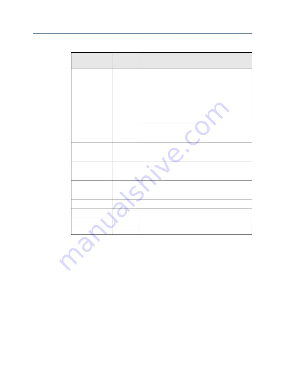
Table J-13. Output Variables for the Configurable Floating Point Format (Default Code
1)
The Rosemount 5300 Series register area starting with register 2000 is used for hosts that
require Floating Point Format Code 0 (see
).
Floating Point Format Codes 2 and 3 use register areas 2100 and 2200, respectively (see
).
Register Name
Register
Number
Note
Slave 1 Status Conf
1300
Bit information in bitfield.
Bit 0: Invalid Measurement Slave 1 PV.
Bit 1: Invalid Measurement Slave 1 Non PV.
Bit 2: Invalid Measurement Slave 1 Non PV.
Bit 3: Invalid Measurement Slave 1 Non PV.
Bit 14: HART bus busy (slave in burst or other master
present)
Bit 15: HTM Task not running (option not available).
Note:
Bit 1-3 is set when Invalid Measurement of Slave 1 Non
PV. i.e. all three bits are set simultaneously.
Slave 1 PV Conf
1302
Primary variable from slave 1 represented in IEEE 754
format, using the byte order set in the
FloatingPointFormatCode register.
Slave 1 SV Conf
1304
Secondary variable from slave 1 represented in IEEE 754
format, using the byte order set in the
FloatingPointFormatCode register.
Slave 1 TV Conf
1306
Tertiary variable from slave 1 represented in IEEE 754
format, using the byte order set in the
FloatingPointFormatCode register.
Slave 1 FV Conf
1308
Fourth variable from slave 1 represented in IEEE 754 format,
using the byte order set in the FloatingPointFormatCode
register.
Slave 2 data
1310-1318
Same data as for Slave 1.
Slave 3 data
1320-1328
Same data as for Slave 1.
Slave 4 data
1330-1338
Same data as for Slave 1.
Slave 5 data
1340-1348
Same data as for Slave 1.


