


3-98
Programming and Parameters
PowerFlex 700S Phase II AC Drive User Manual -
Publication 20D-UM006G-EN-P – July 2008
826
Dig In2 Sel
Enter a value to select the function of digital input 2. Refer to
for a description of
options 34 “UserGen Sel0” - 37 “UserGen Sel3”.
Note:
For all Stop Functions: Low = Stop, High = OK to Run, In "Norm Stop-CF" Low =
Normal Stop and Clear Fault.
Notes: Option 38 “ExtFault Inv” was added for firmware version 2.04. Option 39 “Home
Switch” was added for firmware version 3.01. Values 41 and 42 were added for
firmware version 4.001.
Default:
Options:
0 =
0 =
1 =
2 =
3 =
4 =
5 =
6 =
7 =
8 =
9 =
10 =
11 =
12 =
13 =
14 =
15 =
16 =
17 =
18 =
19 =
20 =
“Not Used”
“Not Used”
21 = “Indx Step”
“Enable”
22 = “Indx StepRev”
“Clear Faults”
23 = “MOP Inc”
“Ext Fault”
24 = “MOP Dec”
“Norm Stop-CF”
25 = “MOP Reset”
“Start”
26 = “PI Trim En”
“Reverse”
27 = “PI Trim Hold”
“Run”
28 = “PI Trim Rst”
“Reserved”
29 = “Trend Trig”
“Reserved”
30 = “PreCharge En”
“Jog 1”
31 = “Regis 2 Ltch”
“Reserved”
32 = “+Hrd OvrTrvl”
“Reserved”
33 = “-Hrd OvrTrvl”
“Jog 2”
34 = “UserGen Sel0”
“Normal Stop”
35 = “UserGen Sel1”
“Spd Ref Sel0”
36 = “UserGen Sel2”
“Spd Ref Sel1”
37 = “UserGen Sel3”
“Spd Ref Sel2”
38 = “ExtFault Inv”
“CurLim Stop”
39 = “Home Switch”
“Coast Stop”
41 = “Find Home”
“Accel Decel2”
42 = “Return Home”
827
828
829
830
Dig In3 Sel
Enter a value to select the function of digital input 3.
Dig In4 Sel
Enter a value to select the function of digital input 4.
Dig In5 Sel
Enter a value to select the function of digital input 5.
Dig In6 Sel
Enter a value to select the function of digital input 6.
Refer to
for a description of options 34 “UserGen Sel0” - 37 “UserGen Sel3”.
Note:
For all Stop Functions: Low = Stop, High = OK to Run, In "Norm Stop-CF" Low =
Normal Stop and Clear Fault.
Note:
Notes: Option 38 “ExtFault Inv” was added for firmware version 2.04. Option 39
“Home Switch” was added for firmware version 3.01. Values 41 and 42 were added
and value 39 was deleted for firmware version 4.001.
(1)
Opening an “Enable” input will cause the motor to coast-to-stop, ignoring any programmed
Stop modes.
Default:
Options:
0 =
0 =
1 =
2 =
3 =
4 =
5 =
6 =
7 =
8 =
9 =
10 =
11 =
12 =
13 =
14 =
15 =
16 =
17 =
18 =
19 =
20 =
“Not Used”
“Not Used”
21 = “Indx Step”
“Enable”
(1)
22 = “Indx StepRev”
“Clear Faults”
23 = “MOP Inc”
“Ext Fault”
24 = “MOP Dec”
“Norm Stop-CF”
25 = “MOP Reset”
“Start”
26 = “PI Trim En”
“Reverse”
27 = “PI Trim Hold”
“Run”
28 = “PI Trim Rst”
“Reserved”
29 = “Trend Trig”
“Reserved”
30 = “PreCharge En”
“Jog 1”
31 = “Reserved”
“Reserved”
32 = “+Hrd OvrTrvl”
“Reserved”
33 = “-Hrd OvrTrvl”
“Jog 2”
34 = “UserGen Sel0”
“Normal Stop”
35 = “UserGen Sel1”
“Spd Ref Sel0”
36 = “UserGen Sel2”
“Spd Ref Sel1”
37 = “UserGen Sel3”
“Spd Ref Sel2”
38 = “ExtFault Inv”
“CurLim Stop”
39 = “Reserved”
“Coast Stop”
41 = “Find Home”
“Accel Decel2”
42 = “Return Home”
831
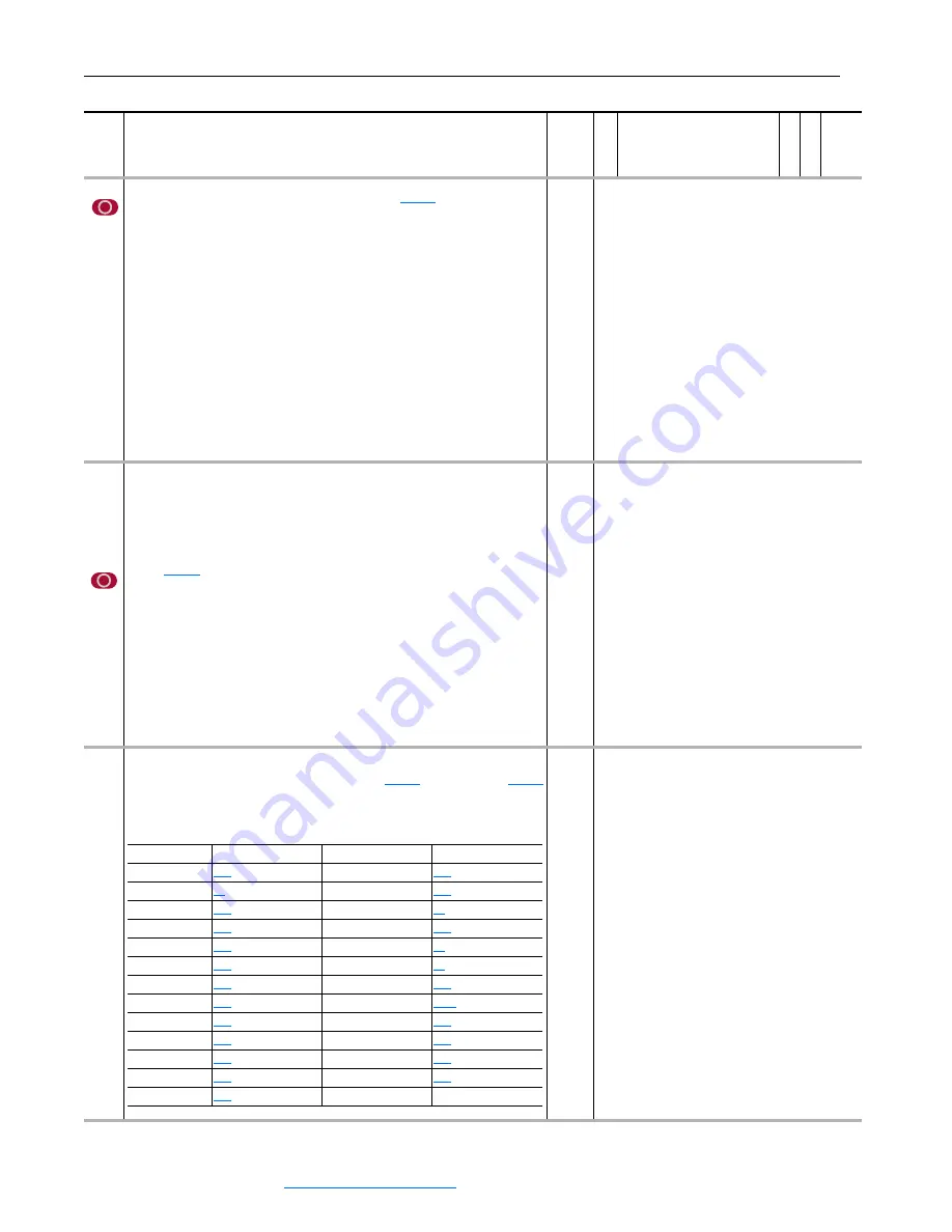
Anlg Out1 Sel
Identifies the signal used on Analog Output 1. If the desired signal is not available in the
selection list, choose option 0 - “User Select” and link with
[Anlg Out1 Real] to select the desired parameter for output.
The following table provides the parameter that corresponds to the option selected in this
parameter.
Default:
Options:
17 =
0 =
1 =
2 =
3 =
4 =
5 =
6 =
7 =
8 =
9 =
10 =
11 =
12 =
13 =
“Speed Fdbk”
“User Select”
14 = “Reserved”
“Output Freq”
15 = “Motor TrqRef”
“Sel Spd Ref”
16 = “MtrTrqCurRef”
“Output Curr”
17 = “Speed Ref”
“Trq Cur (Iq)”
18 = “Speed Fdbk”
“% Motor Flux”
19 = “Torque Est”
“Output Power”
20 = “Scl Spd Fdbk”
“Output Volts”
21 = “RampedSpdRef”
“DC Bus Volts”
22 = “Spd Reg Out”
“PI Reference”
23 = “MOP Level”
“PI Feedback”
24 = “Trend 1 DInt”
“PI Error”
25 = “Trend 1 Real”
“PI Output”
26 = “Trend 2 DInt”
“Reserved”
27 = “Trend 2 Real”
No.
Name
Description
Values
Linkab
le
R
ead-Wr
ite
Da
ta
T
ype
Option
Parameter
Option
Parameter
1 “Output Freq”
16 “MtrTrqCurRef”
[Mtr Trq Curr Ref]
2 “Sel Spd Ref”
[Selected Spd Ref] 17 “Speed Ref”
[Motor Speed Ref]
3 “Output Curr”
18 “Speed Fdbk”
[Filtered SpdFdbk]
4 “Trq Cur (Iq)”
[Trq Cur Fdbk (Iq)] 19 “Torque Est”
[Estimated Torque]
5 “% Motor Flux”
20 “Scl Spd Fdbk”
[Scaled Spd Fdbk]
6 “Output Power”
21 “RampedSpdRef”
[Ramped Spd Ref]
7 “Output Volts”
22 “Spd Reg Out”
[SpdReg Integ Out]
8 “DC Bus Volts”
[DC Bus Voltage]
23 “MOP Level”
[MOP Level Real]
9 “PI Reference”
24 “Trend 1 DInt”
[Trend Out1 DInt]
10 “PI Feedback”
25 “Trend 1 Real”
[Trend Out1 Real]
11 “PI Error”
26 “Trend 2 DInt”
[Trend Out2 DInt]
12 “PI Output”
27 “Trend 2 Real”
[Trend Out2 Real]
15 “Motor TrqRef”
[Motor Torque Ref]


