AirPick - Instruction Manual
l
Major faults (0xA <= gFLT <= 0xF) - Reset is required (rising edge on activation bit rACT required)
o
0xA - Under minimum operating voltage.
o
0xB - Automatic release in progress (Vacuum/pressure detected).
o
0xC - Internal fault; contact
.
o
0xF - Automatic release completed (Vacuum/pressure not detected)
kFLT
Please refer to the optional Robotiq Controller manual (input registers & status).
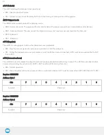
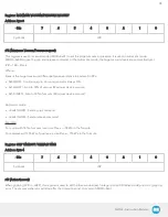
Register: MAXIMUM VACUUM/PRESSURE LEVEL REQUEST ECHO
Address: Byte 3
Bits
7
6
5
4
3
2
1
0
Symbols
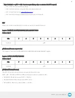
gPR
gPR (Vacuum/Pressure request echo)
This register is the echo of the MAXIMUM VACUUM/PRESSURE LEVEL REQUEST register.
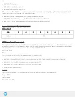
Register: ACTUAL VACUUM/PRESSURE
Address: Byte 4
Bits
7
6
5
4
3
2
1
0
Symbols
gPO
gPO (Actual Vacuum/Pressure)
The gPO is the actual vacuum/pressure measured in the suction cups.
Pdiff = gPO - 100. Where Pdiff is the differential pressure relative to ambient in KPa.
l
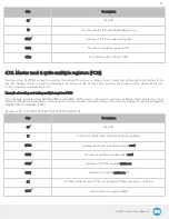
0x00 (0d00) - Maximum vacuum (Pdiff <= -100 kPa).
l
0x64 (0d100) - No differential pressure (Pdiff = 0 kPa).
l
0xFF (0d255) - Maximum pressure (Pdiff >= 155 kPa).
42
Summary of Contents for AirPick
Page 25: ...Fig 3 7 Mounting air nodes suction cups air bolts air nuts on the bracket 25...
Page 27: ...Fig 3 9 Robotiq Vacuum Gripper with pigtail cable and device cable wiring scheme 27...
Page 35: ...Fig 4 1 Vacuum Gripper control logic overview 35...
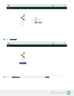
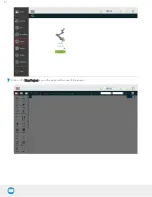
Page 57: ...7 Click on the New Project icon in the upper left corner of the screen 57...
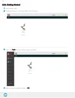
Page 58: ...AirPick Instruction Manual 8 Enter a name for your program and click on the OK button 9 58...
Page 76: ...Fig 6 5 Minimum and maximum arrangement possibilities of the air nodes position 76...
Page 77: ...AirPick Instruction Manual 6 1 3 Air nodes Fig 6 6 Air nodes dimensions 77...
Page 103: ...AirPick Instruction Manual 12 Appendix Fig 12 1 Pneumatic schema of the AirPick Vacuum Gripper...

