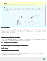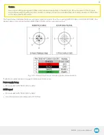
Caution
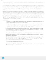
Be careful with the fragile pins while installing the Vacuum Gripper onto the I/O Coupling. Any abrupt movement can
damage the pins and lead to product malfunction.
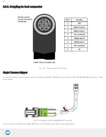
2. Plug the I/O Coupling connector into the robot tool flange connector.
Caution
Make sure to close the silicone door of the I/O coupling micro-USB port to prevent any dust or liquid infiltration.
Firmware Update
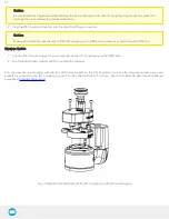
1. Connect the Vacuum Gripper to your computer via the I/O Coupling using the USB cable.
2. Run the Robotiq User Interface (RUI) to update the firmware.
You can now use your Gripper with the four (4) factory presets on the I/O Coupling. You can also program and save your own
presets by connecting the I/O Coupling to your PC using the USB cable. To do so, refer to the Robotiq User Interface Manual
available at
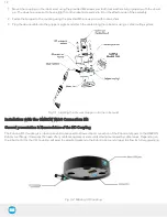
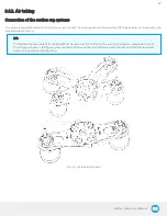
Fig. 3-3: Mechanical installation of the I/O Coupling and the Vacuum Gripper
21
Summary of Contents for AirPick
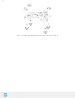
Page 25: ...Fig 3 7 Mounting air nodes suction cups air bolts air nuts on the bracket 25...
Page 27: ...Fig 3 9 Robotiq Vacuum Gripper with pigtail cable and device cable wiring scheme 27...
Page 35: ...Fig 4 1 Vacuum Gripper control logic overview 35...
Page 57: ...7 Click on the New Project icon in the upper left corner of the screen 57...
Page 58: ...AirPick Instruction Manual 8 Enter a name for your program and click on the OK button 9 58...
Page 76: ...Fig 6 5 Minimum and maximum arrangement possibilities of the air nodes position 76...
Page 77: ...AirPick Instruction Manual 6 1 3 Air nodes Fig 6 6 Air nodes dimensions 77...
Page 103: ...AirPick Instruction Manual 12 Appendix Fig 12 1 Pneumatic schema of the AirPick Vacuum Gripper...


