


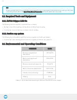


AirPick - Instruction Manual
Caution
Use proper cabling management. Make sure to leave enough slack in the cabling to allow movement of the Gripper
along all axes without pulling out the connectors. Always protect the controller side (robot side) connector of the cable
with a strain relief cable clamp.
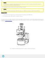
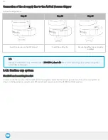
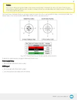
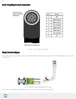
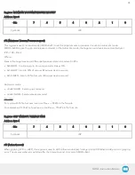
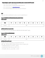
The figure below illustrates the Vacuum Gripper pigtail connector from the coupling (GRP-CPL-062 or AGC-CPL-XXX-002), the
device cable on the robot side (CBL-COM-2065-10-HF) and their associated pinout.
Fig. 3-10: Pinout of the Vacuum Gripper pigtail and device cable
If additional cables are used, suggested cable specifications are:
Power supply, fusing
l
Minimum #22 AWG TEW, 300 V or 600 V
RS485 signal
l
Minimum #24 AWG TEW, 300 V or 600 V
l
A and B signals must be balanced at 120 Ohms
28
Summary of Contents for AirPick
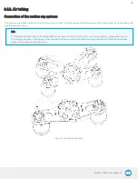
Page 25: ...Fig 3 7 Mounting air nodes suction cups air bolts air nuts on the bracket 25...
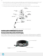
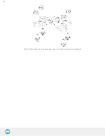
Page 27: ...Fig 3 9 Robotiq Vacuum Gripper with pigtail cable and device cable wiring scheme 27...
Page 35: ...Fig 4 1 Vacuum Gripper control logic overview 35...
Page 57: ...7 Click on the New Project icon in the upper left corner of the screen 57...
Page 58: ...AirPick Instruction Manual 8 Enter a name for your program and click on the OK button 9 58...
Page 76: ...Fig 6 5 Minimum and maximum arrangement possibilities of the air nodes position 76...
Page 77: ...AirPick Instruction Manual 6 1 3 Air nodes Fig 6 6 Air nodes dimensions 77...
Page 103: ...AirPick Instruction Manual 12 Appendix Fig 12 1 Pneumatic schema of the AirPick Vacuum Gripper...