l
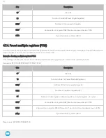
0x00 (0d0) - No timeout.
l
0x0A (0d10) - 1 sec timeout period.
l
0xFF (0d255) - 25.5 sec timeout period.
When releasing (rPR >= 0d100), this register is used to set the time window (each integer being 100 milliseconds) prior to set the
vacuum actuators in holding mode. Only valid if rMOD=0x01.
l
0x00 (0d0) - Vacuum holding state set when ambient pressure is detected.
l
0x01 (0d01) - Vacuum holding state set 100 msec after ambient pressure is detected.
l
0x0A (0d10) - Vacuum holding state set 1000 msec after ambient pressure is detected.
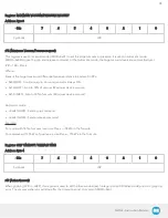
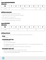
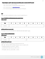
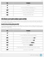
Register: MINIMUM VACUUM/PRESSURE REQUEST
Address: Byte 5
Bits
7
6
5
4
3
2
1
0
Symbols
rFR
rFR (Minimum Vacuum/Pressure request)
This register is used to set the appropriate minimum acceptable vacuum/pressure on the workpiece. When the minimum vacuum
level is reached, the object flag (gOBJ) will be set. Once the object is detected, the vacuum generator will keep the vacuum level
in between the minimum and maximum vacuum level. Only valid if rMOD=0x01.
rFR = 100 + Pmin.
Where:
P
min
is the target minimum differential pressure relative to ambient in kPa.
l
0x00 (0d0) - Object will be detected when vacuum level reaches 100% (This is impossible, so avoid using this value)
l
0x1E (0d30) - Object will be detected when vacuum level reaches 70%.
l
0x50 (0d80) - Object will be detected when vacuum level reaches 20%.
l
>0x64 (>0d100) - Reserved value
Example:
For a grip with a maximum of 78% vacuum level and an object detection at 20% of vacuum level, use:
Pmax = -78 kPa
Pmin = -20 kPa
rFR = 100 + (-20) = 80
39
Summary of Contents for AirPick
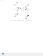
Page 25: ...Fig 3 7 Mounting air nodes suction cups air bolts air nuts on the bracket 25...
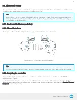
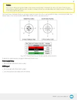
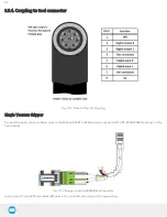
Page 27: ...Fig 3 9 Robotiq Vacuum Gripper with pigtail cable and device cable wiring scheme 27...
Page 35: ...Fig 4 1 Vacuum Gripper control logic overview 35...
Page 57: ...7 Click on the New Project icon in the upper left corner of the screen 57...
Page 58: ...AirPick Instruction Manual 8 Enter a name for your program and click on the OK button 9 58...
Page 76: ...Fig 6 5 Minimum and maximum arrangement possibilities of the air nodes position 76...
Page 77: ...AirPick Instruction Manual 6 1 3 Air nodes Fig 6 6 Air nodes dimensions 77...
Page 103: ...AirPick Instruction Manual 12 Appendix Fig 12 1 Pneumatic schema of the AirPick Vacuum Gripper...

