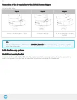
Connection of the air supply line to the AirPick Vacuum Gripper
Follow the steps below:
Step #1
Step #2
Step #3
Insert the air tube in the AirPick port
Insert the safety clip
Ensure the safety clip is properly
installed
Info
Use dry and filtered air only. Follow standard ISO 8573-1, class 3.4.3. We recommend using a local pressure regulator
with a filter and air dryer.
3.4.3. Suction cup system
Manifold and mounting bracket
In order to use the two (2) or the four (4) Suction Cups System, assemble the vacuum generator to the suction cup system, as
shown in the figure below, using four (4) M5 socket head cap screws and four (4) M5 toothlock washers.
23
Summary of Contents for AirPick
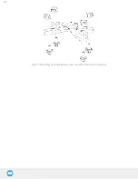
Page 25: ...Fig 3 7 Mounting air nodes suction cups air bolts air nuts on the bracket 25...
Page 27: ...Fig 3 9 Robotiq Vacuum Gripper with pigtail cable and device cable wiring scheme 27...
Page 35: ...Fig 4 1 Vacuum Gripper control logic overview 35...
Page 57: ...7 Click on the New Project icon in the upper left corner of the screen 57...
Page 58: ...AirPick Instruction Manual 8 Enter a name for your program and click on the OK button 9 58...
Page 76: ...Fig 6 5 Minimum and maximum arrangement possibilities of the air nodes position 76...
Page 77: ...AirPick Instruction Manual 6 1 3 Air nodes Fig 6 6 Air nodes dimensions 77...
Page 103: ...AirPick Instruction Manual 12 Appendix Fig 12 1 Pneumatic schema of the AirPick Vacuum Gripper...


