AirPick - Instruction Manual
The status LED, integrated in the micro-USB port presented in the figure above, will be:
l
Solid blue/red when booting
l
Solid red when looking for product or waiting for communication
l
Solid blue when powered with no errors (while communication is active)
l
Solid green when communicating with USB
The I/O Coupling comes with four (4) factory presets, as shown in the table below. These four (4) presets can be reconfigured on a
computer before using them on a robot.
Preset 1
Preset 2
Preset 3
Preset 4
Grip in Auto mode
Continuous grip
Min: 10
Max: 20
Release in Auto mode
Table 3-2: Factory presets for Vacuum Grippers
Safety
Warning
When changing the Vacuum Gripper, it is important to follow the steps in order:
1. Unplug the I/O Coupling cable.
2. Remove the Gripper with the 4mm hex key.
3. Install the new Vacuum Gripper with the required tools.
4. Plug the I/O Coupling cable in the robot tool connector.
Mechanical Installation
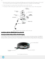
Mounting the I/O Coupling
1. Insert the provided dowel pin into the tool flange. The dowel pin is meant to have a tight fit on the robot side and a slip fit
on the effector side of the assembly.
2. Mount the I/O Coupling on the robot tool flange. Align it properly with the dowel pin.
3. Use the provided M6 screws, the M6 toothlock washers and the 4mm hex key to secure the I/O Coupling installation.
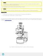
Mounting the Vacuum Gripper onto the I/O Coupling
1. Fasten the Vacuum Gripper onto the I/O Coupling using the M5 screws and toothlock washers of the Gripper.
20
Summary of Contents for AirPick
Page 25: ...Fig 3 7 Mounting air nodes suction cups air bolts air nuts on the bracket 25...
Page 27: ...Fig 3 9 Robotiq Vacuum Gripper with pigtail cable and device cable wiring scheme 27...
Page 35: ...Fig 4 1 Vacuum Gripper control logic overview 35...
Page 57: ...7 Click on the New Project icon in the upper left corner of the screen 57...
Page 58: ...AirPick Instruction Manual 8 Enter a name for your program and click on the OK button 9 58...
Page 76: ...Fig 6 5 Minimum and maximum arrangement possibilities of the air nodes position 76...
Page 77: ...AirPick Instruction Manual 6 1 3 Air nodes Fig 6 6 Air nodes dimensions 77...
Page 103: ...AirPick Instruction Manual 12 Appendix Fig 12 1 Pneumatic schema of the AirPick Vacuum Gripper...


